PCB
The GNUVario project maintain some PCB layout files to help you to build the variometer.
They can be downloaded here.
Here the parameters to give to your PCB manufacturer :
- width : 47 mm ( you can give 50 mm )
- height : 79 mm ( you can give 80 mm )
- thickness : 1.2 mm
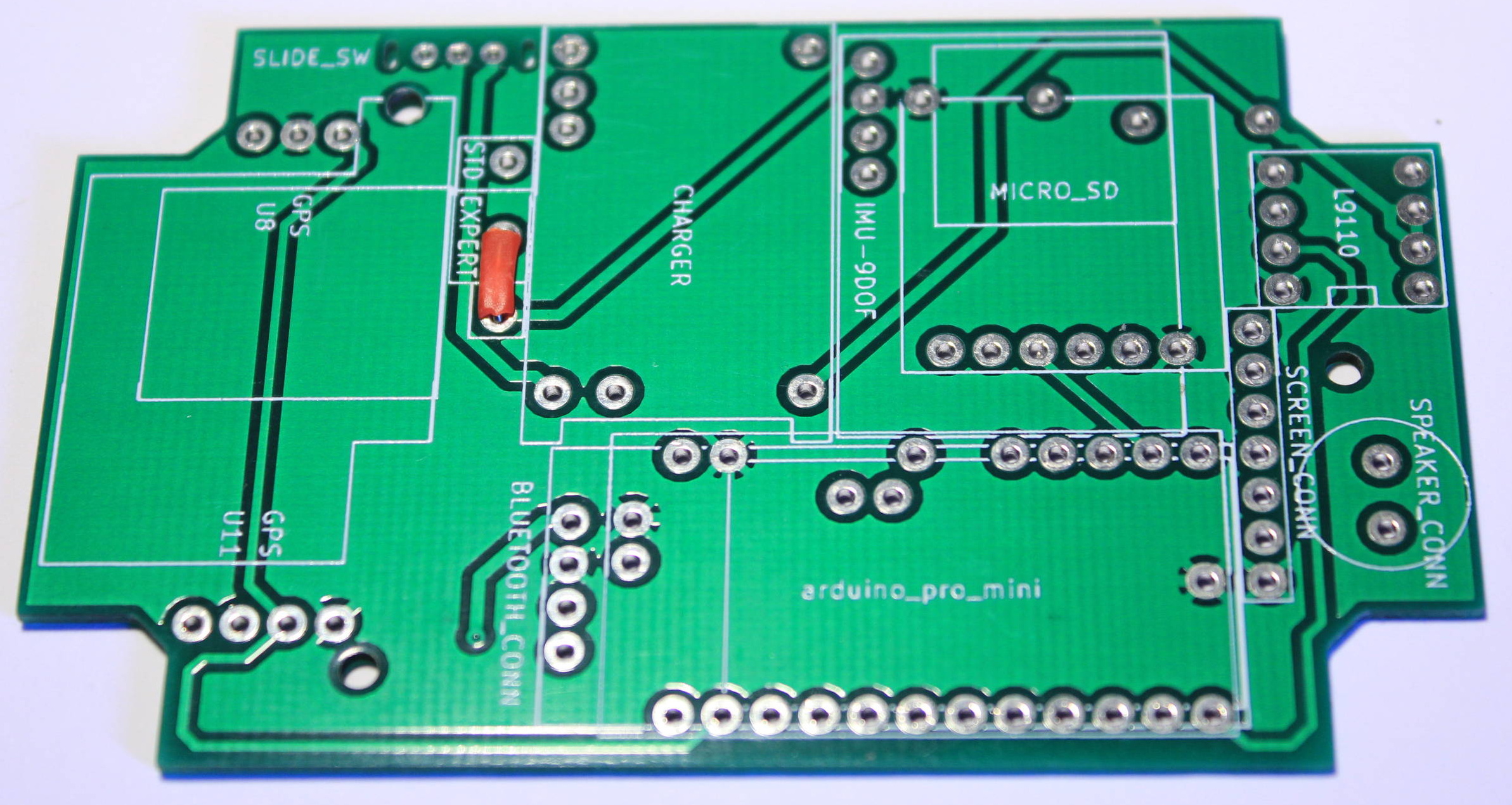
This PCB layout was made with KiCad and the project can be downloaded here.
Warning !
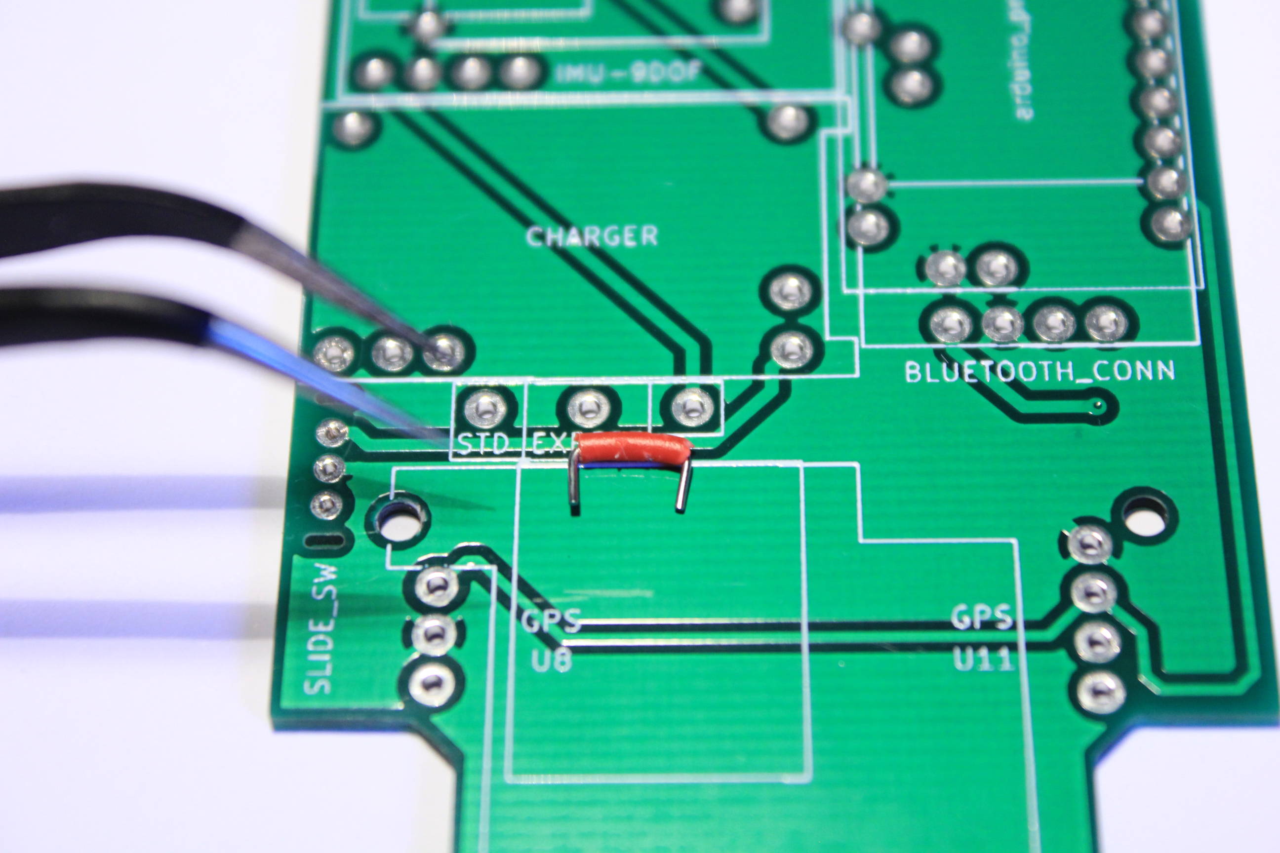
The GNUVario’s PCB come with two possible power modes STANDARD and EXPERT.
In the STANDARD mode all the components boards can be soldered directly. They are powered with the 4.2v power coming from the LiPo battery. As each board have a 3.3v regulator this power source can be used directly.
In the EXPERT mode the components boards are powered with the Arduino’s regulator output. And it’s not fine to power a 3.3v regulators with a 3.3v source as the regulator have some drop-out voltage. So in this mode you need to bypass all the board’s regulators. And you can also change the Arduino’s regulator with a good quality one. This manner you can greatly improve the variometer power consumption.
Here the setup for the STANDARD mode :
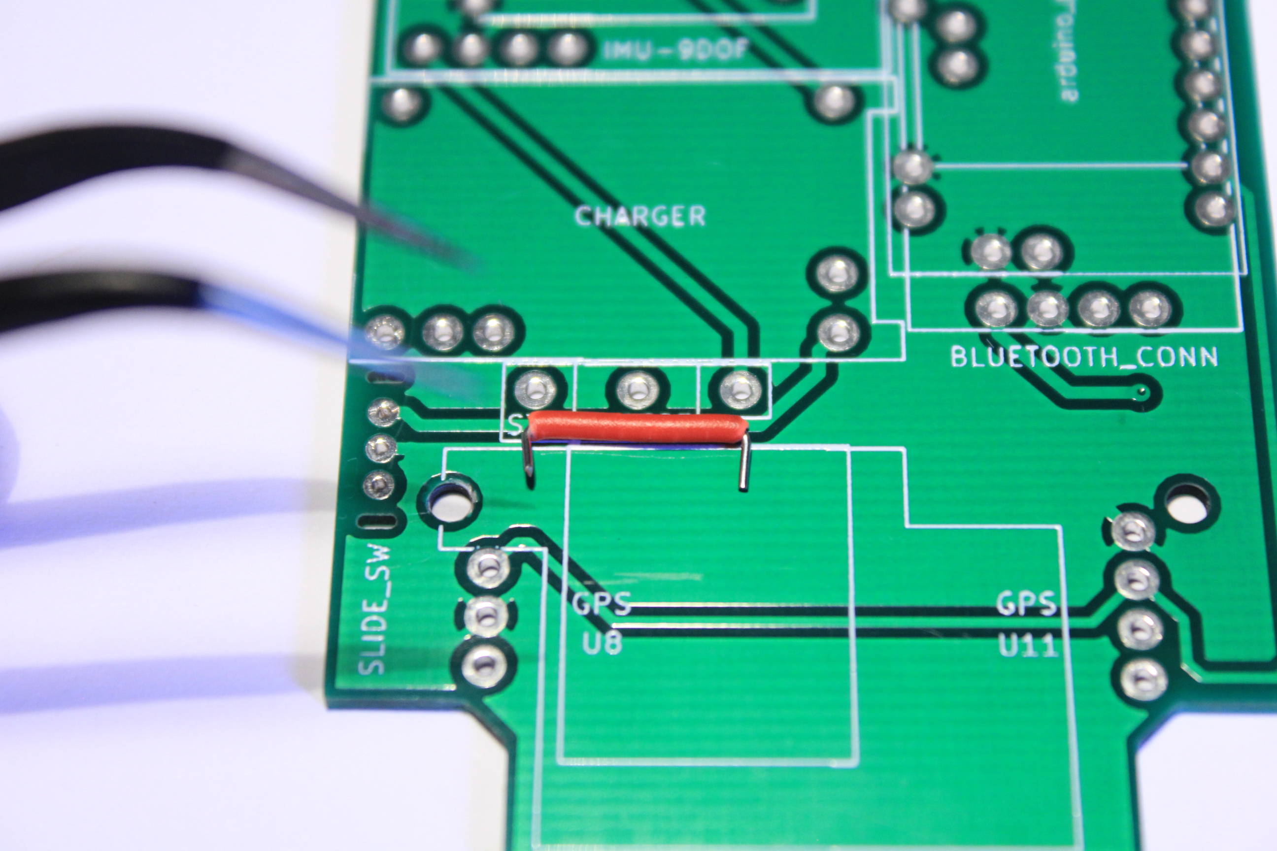
And for the EXPERT mode :