Assembly
Modules soldering
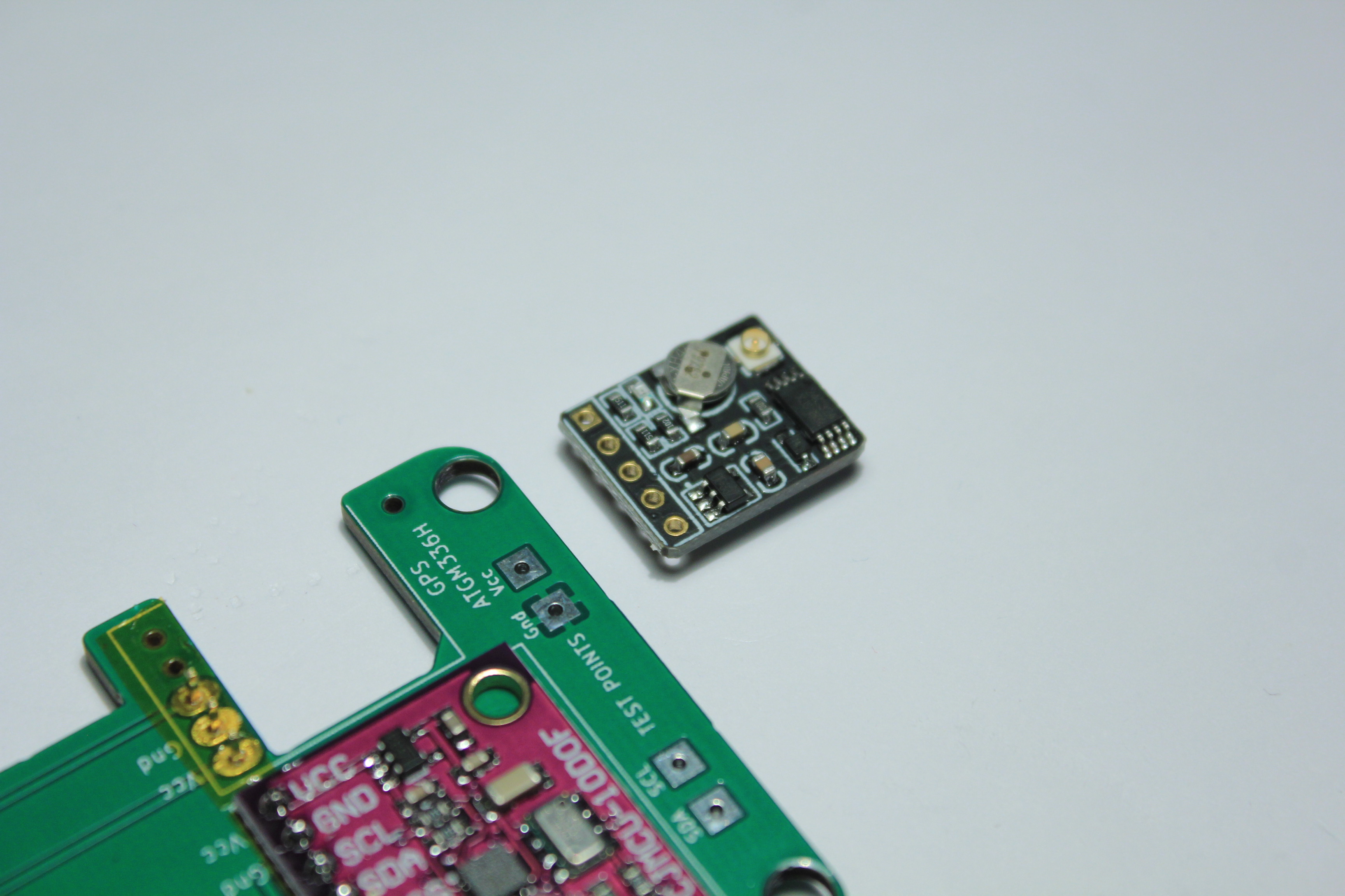
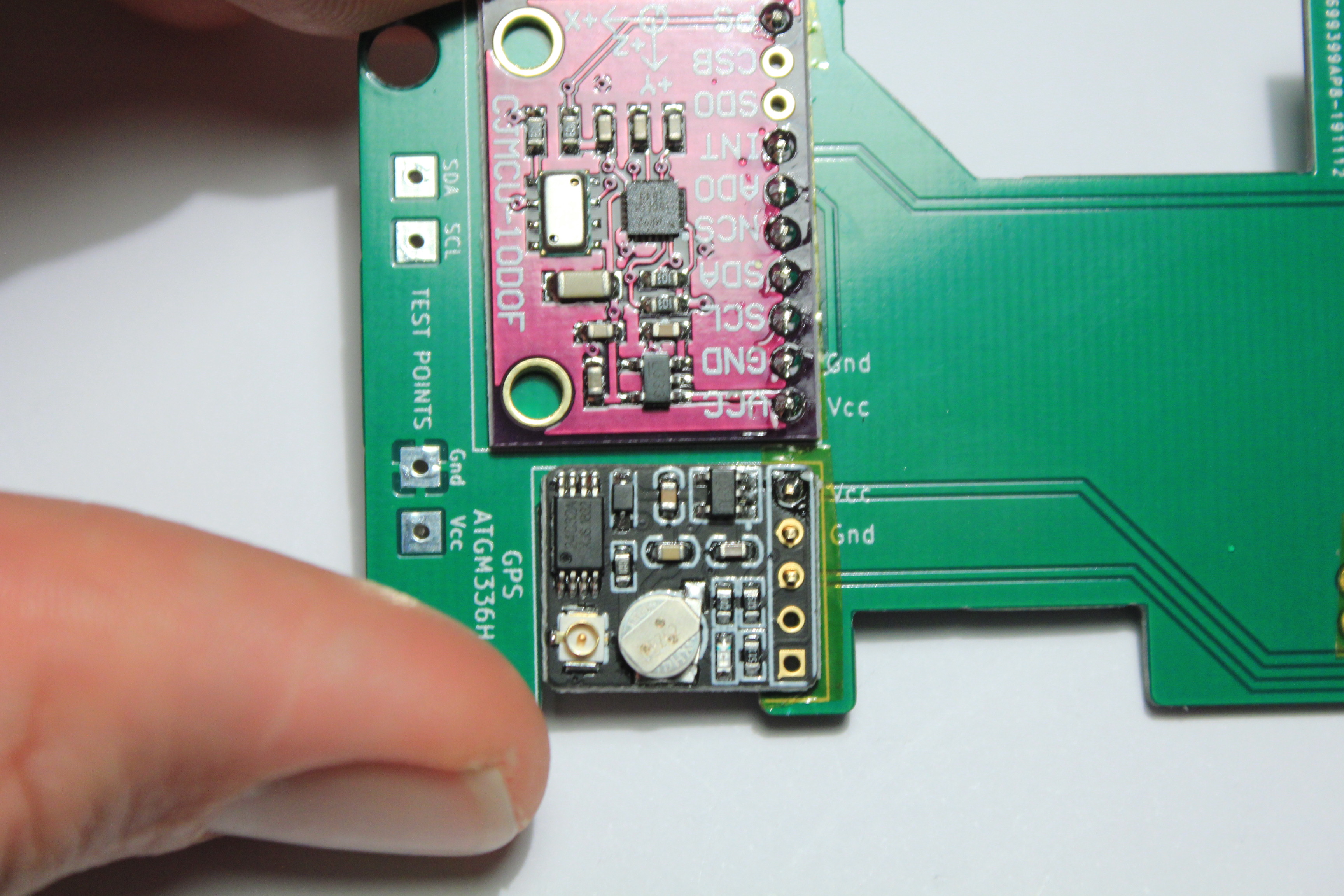
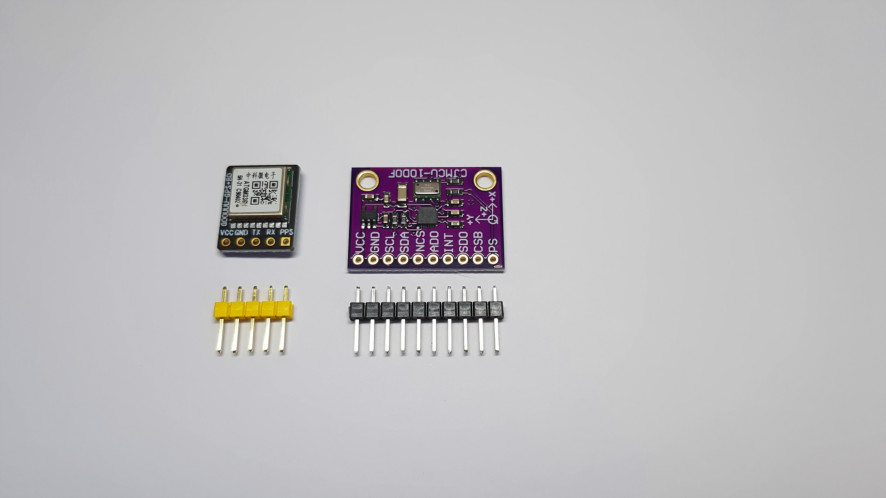
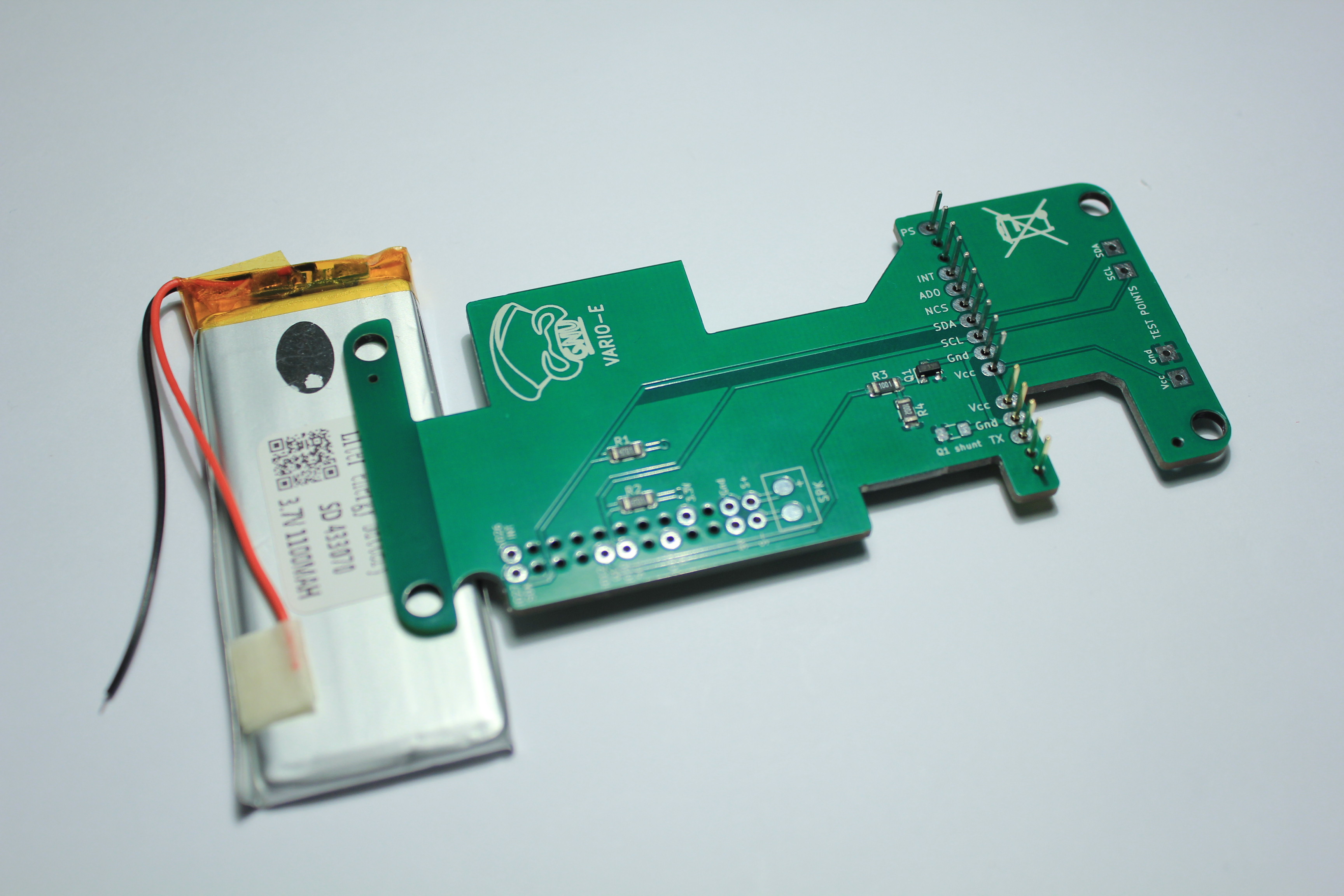
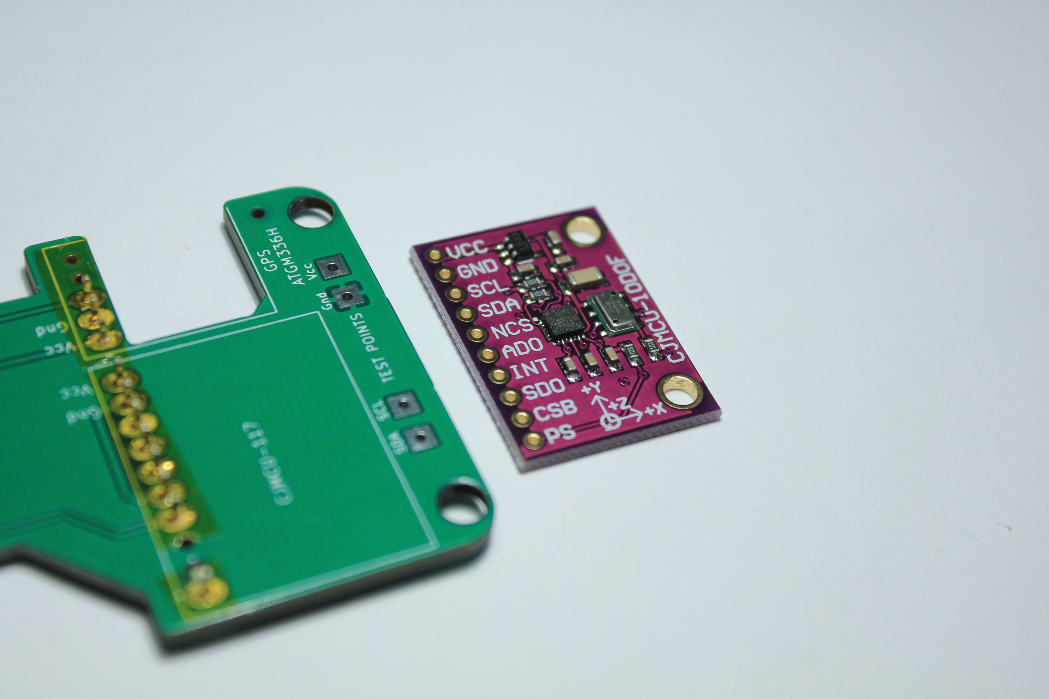
Now take the MPU and the GPS:
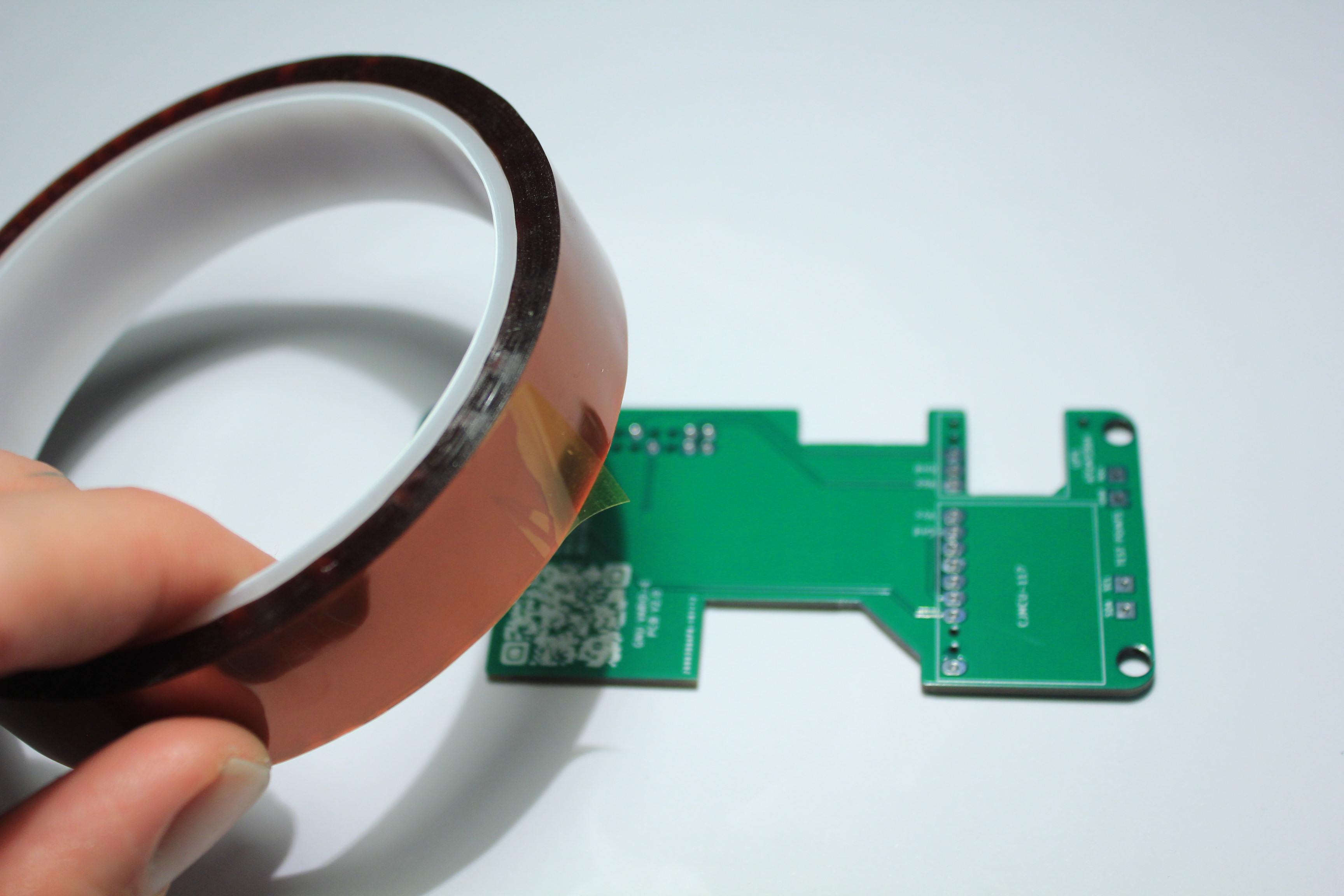
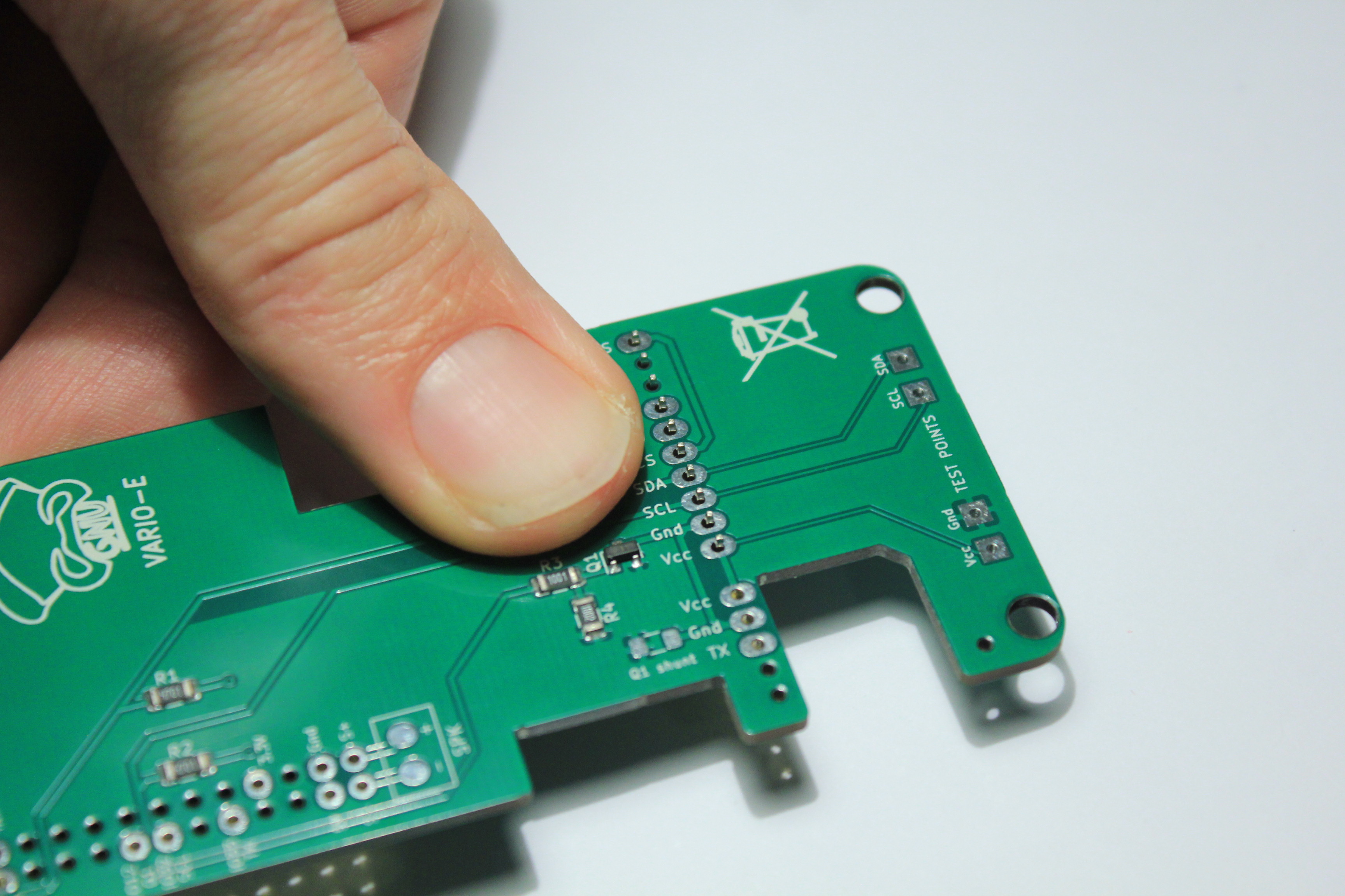
Protect the PCB contacts (face in contact with the boards) with Kapton Tape
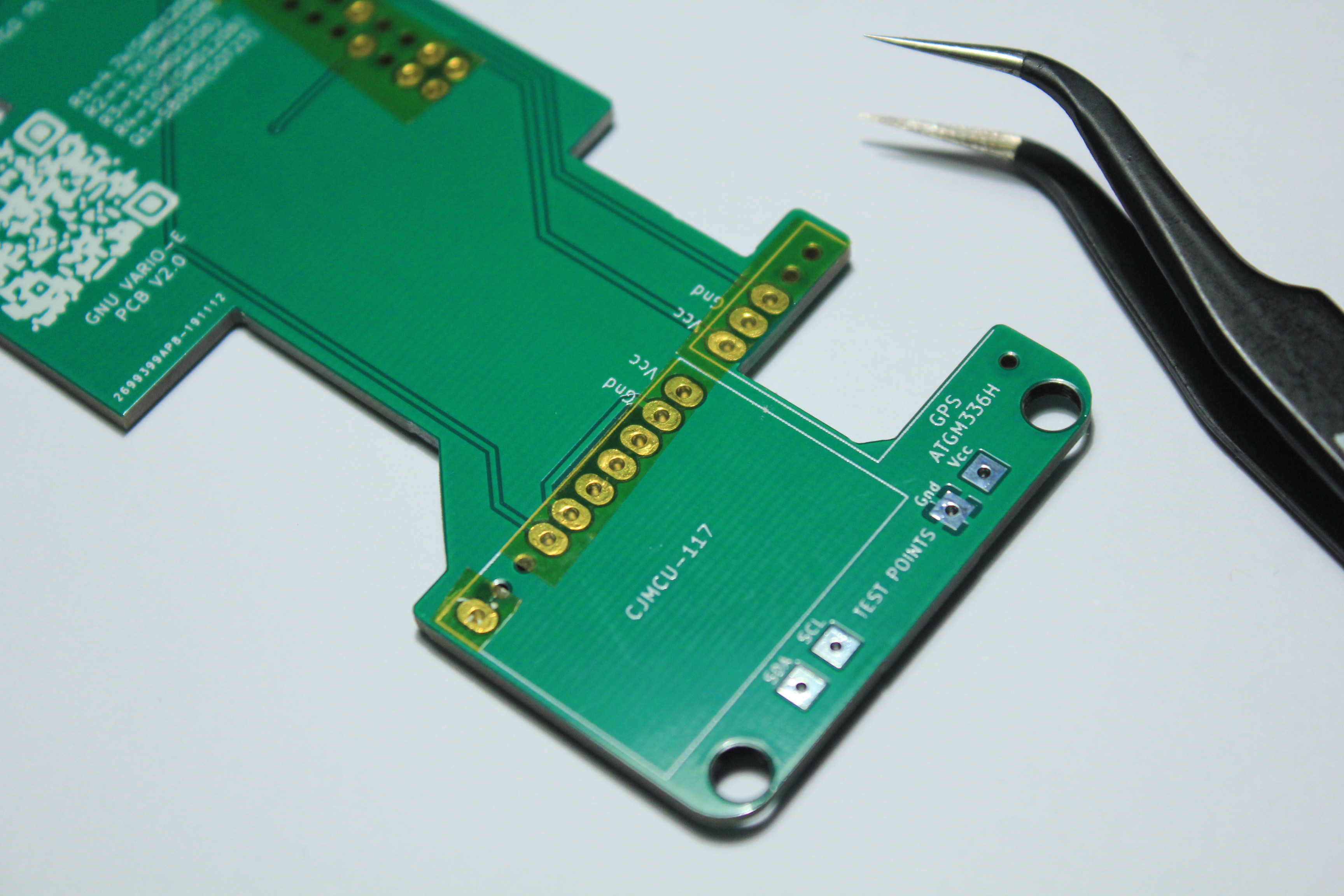
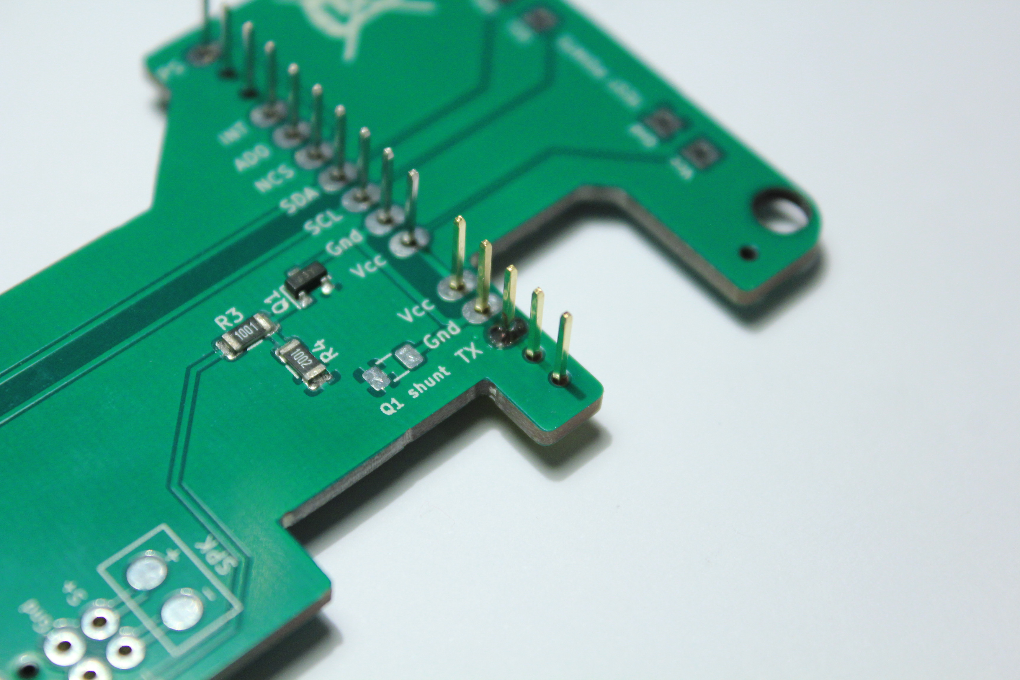
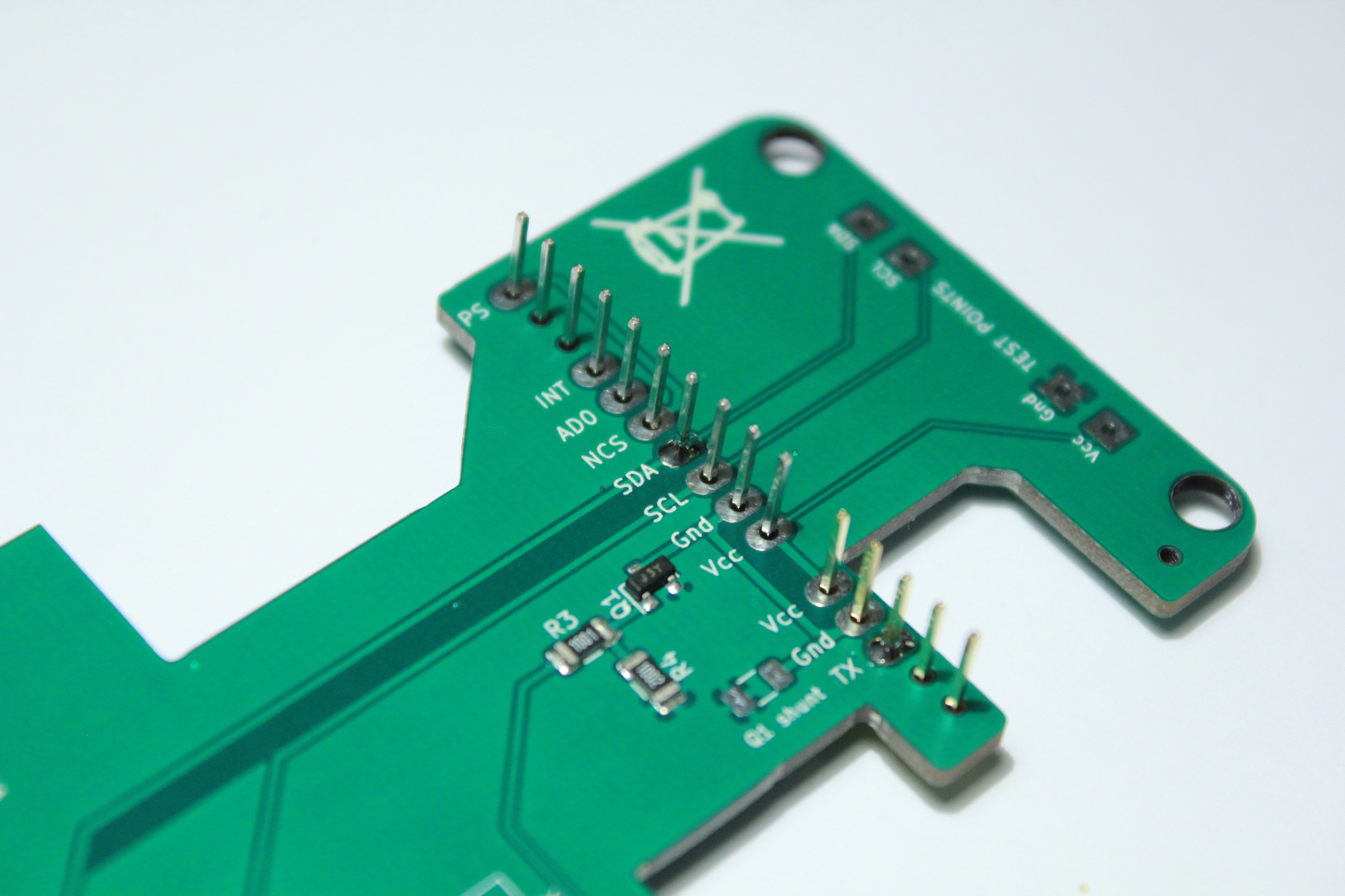
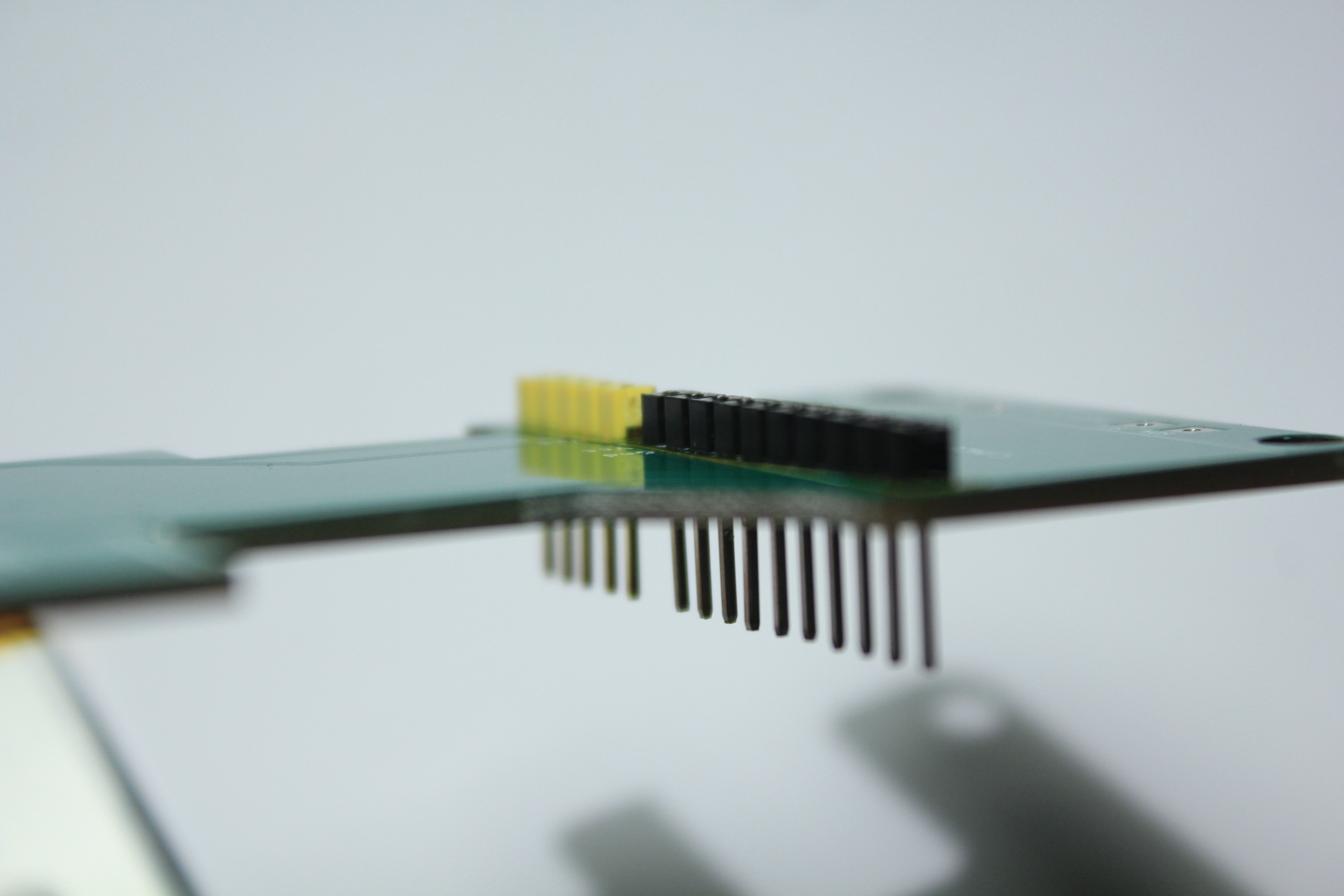
Place the connectors on top of the PCB (long side up).
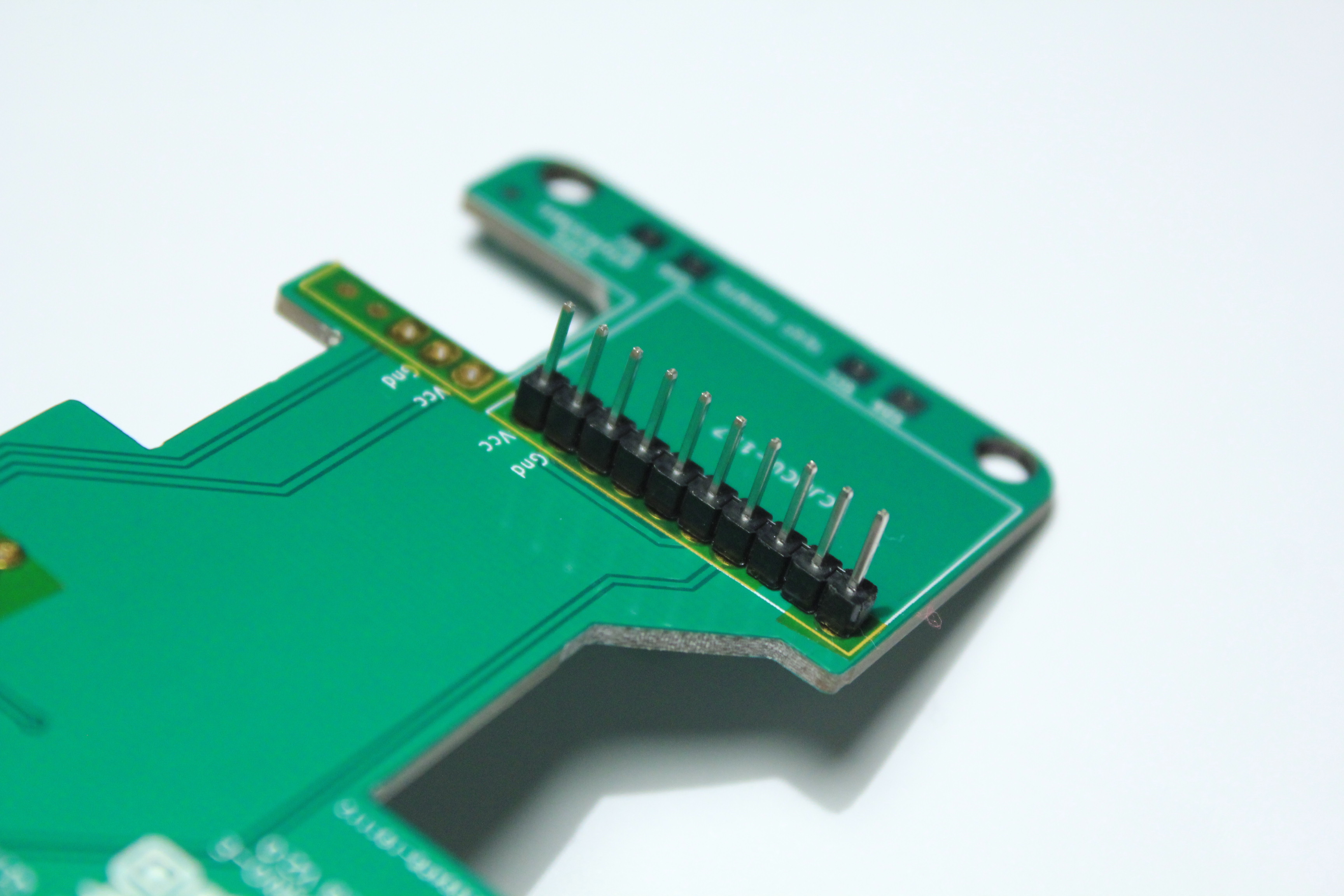
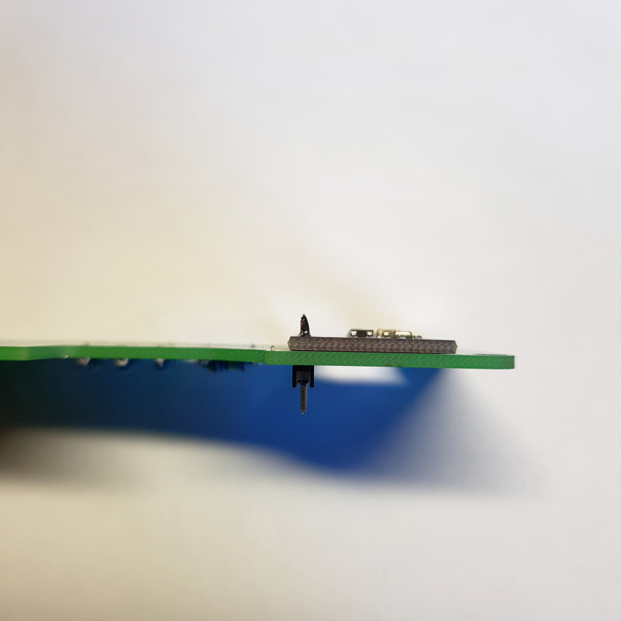
Leaning on a hard surface, push in the pins
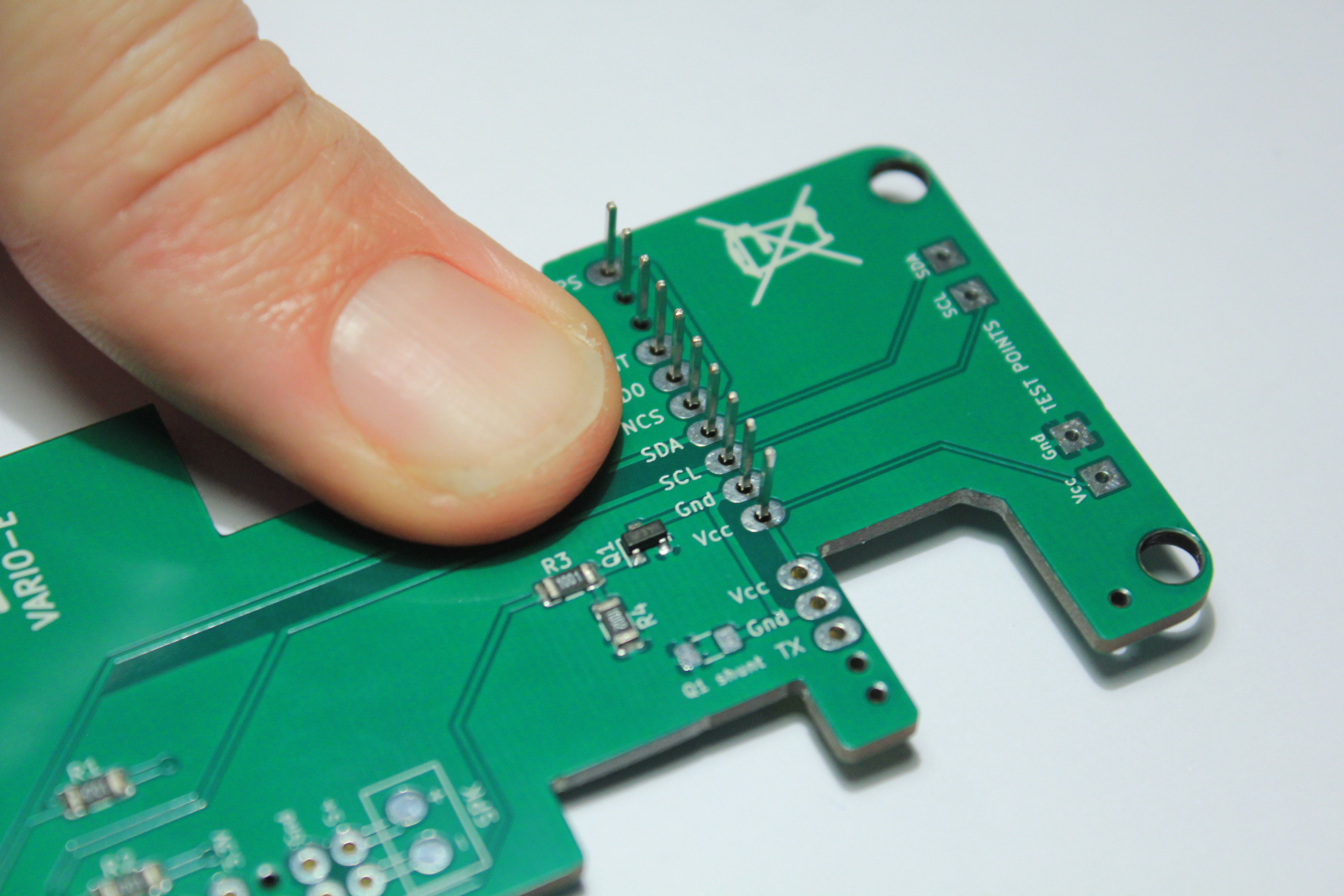
Repeat for the second connector
Fix the PCB with the battery
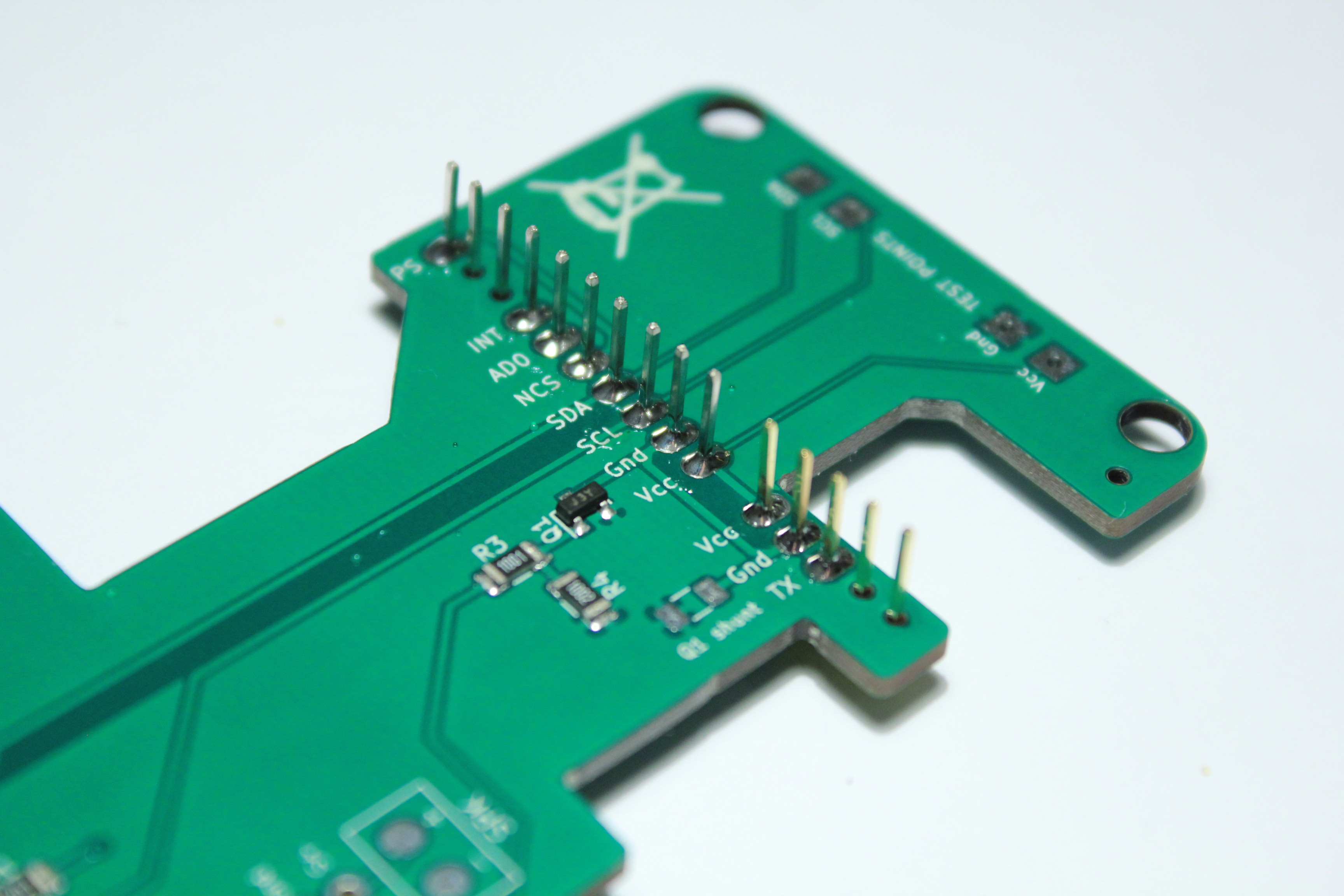
Start by soldering one pin, check its location.
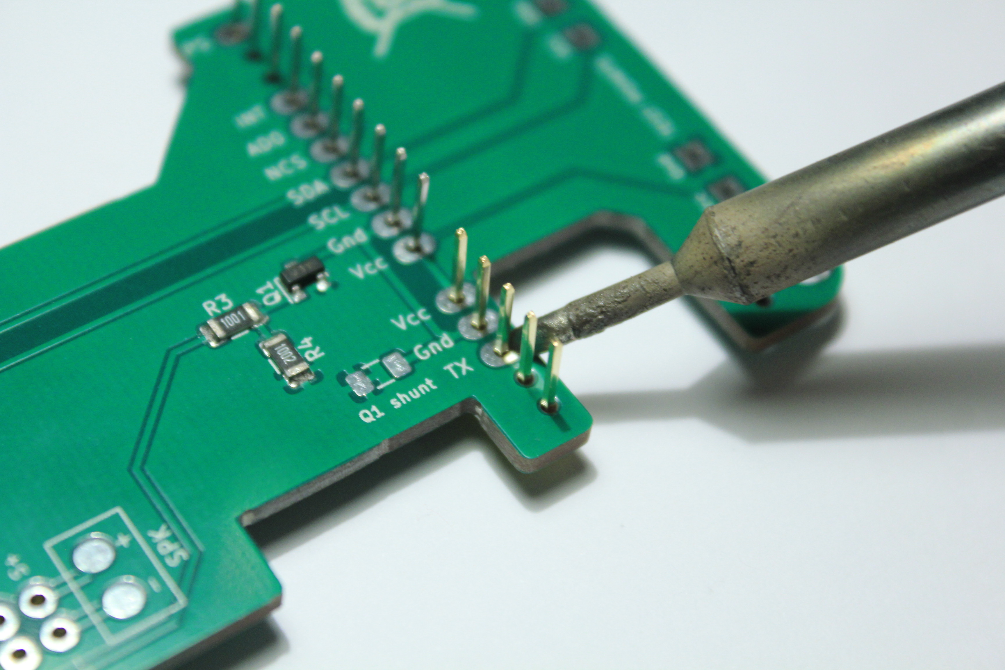
Solder the other pins. Be very careful! Don’t forget some of them.
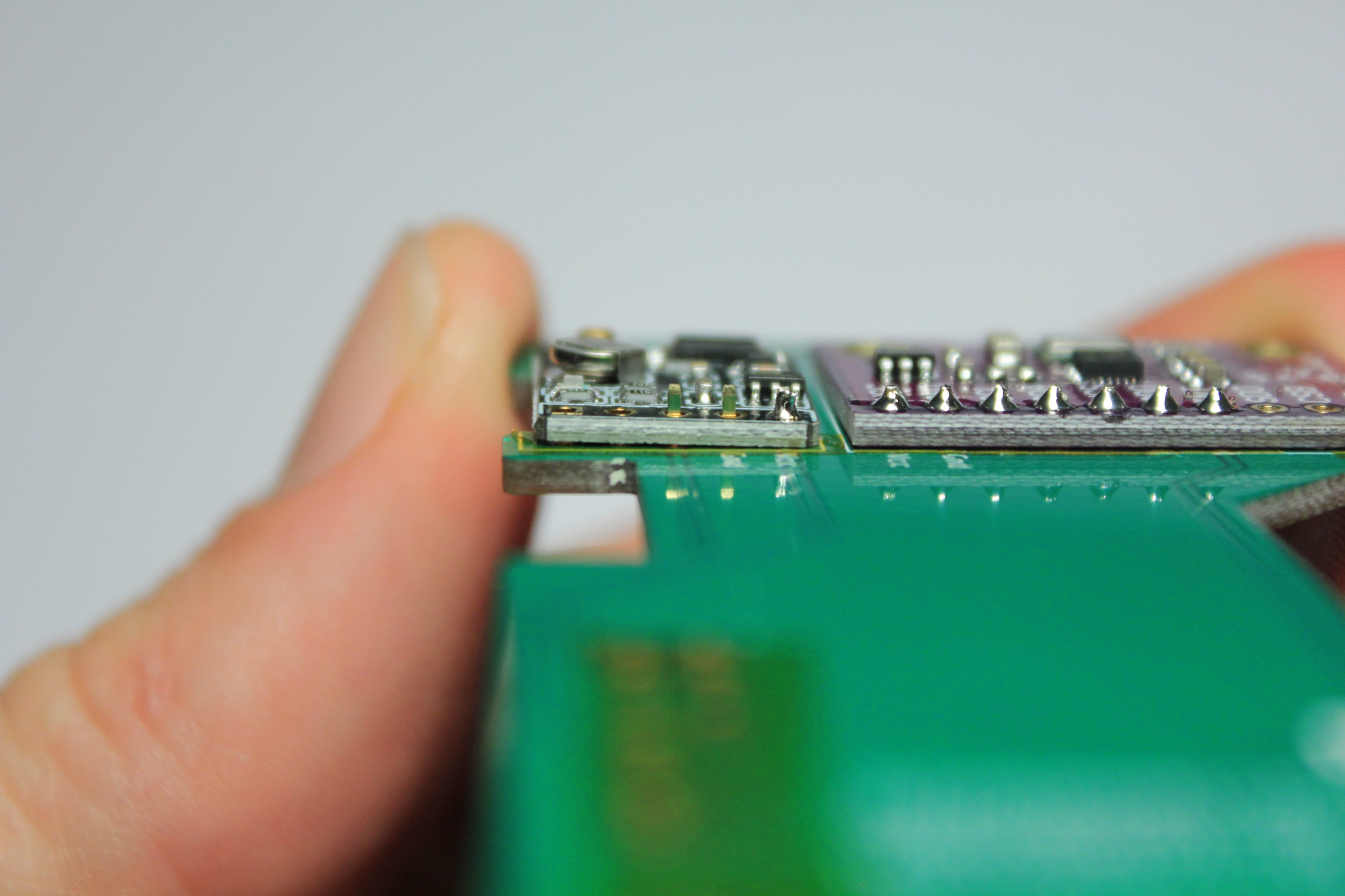
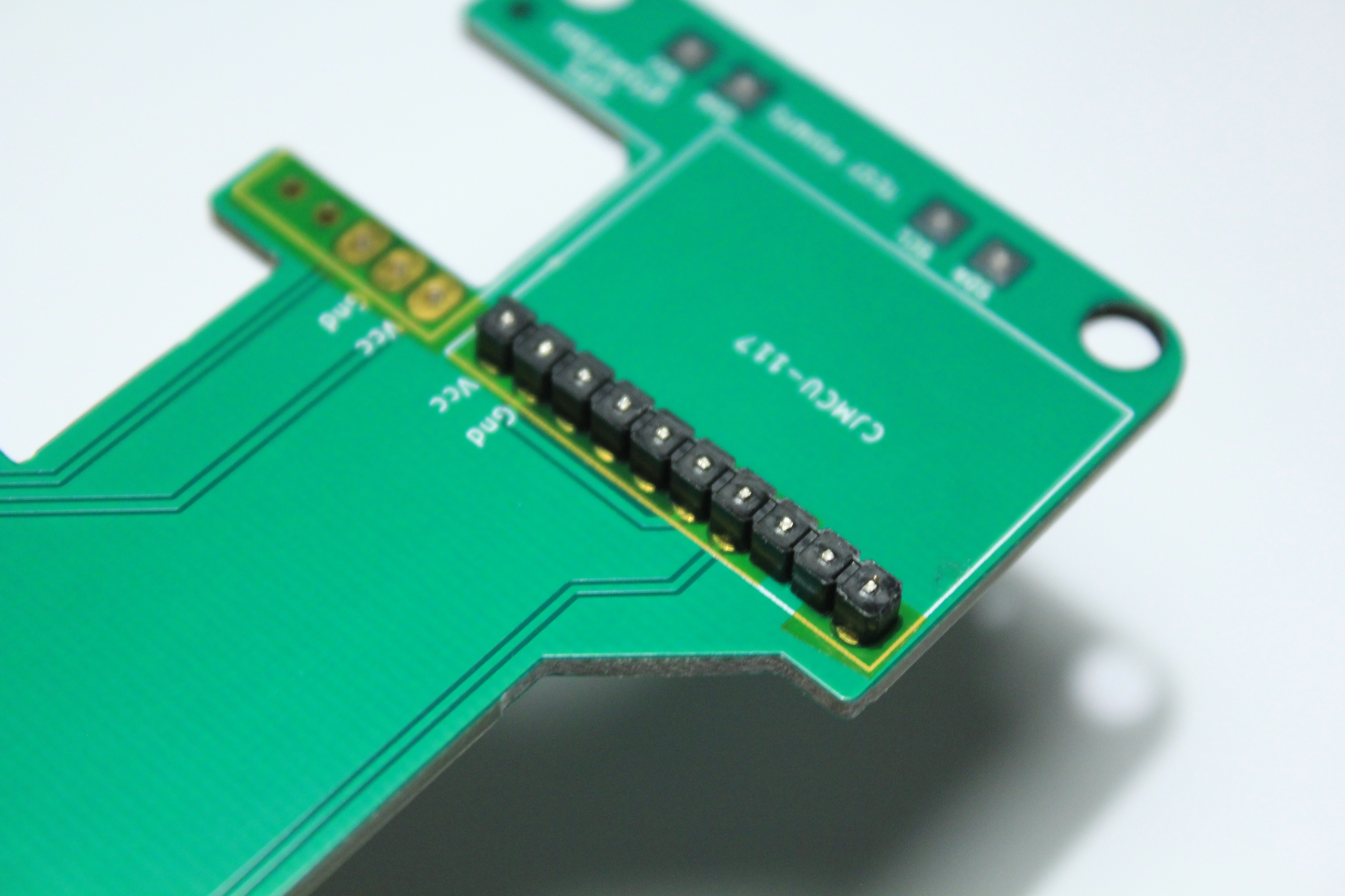
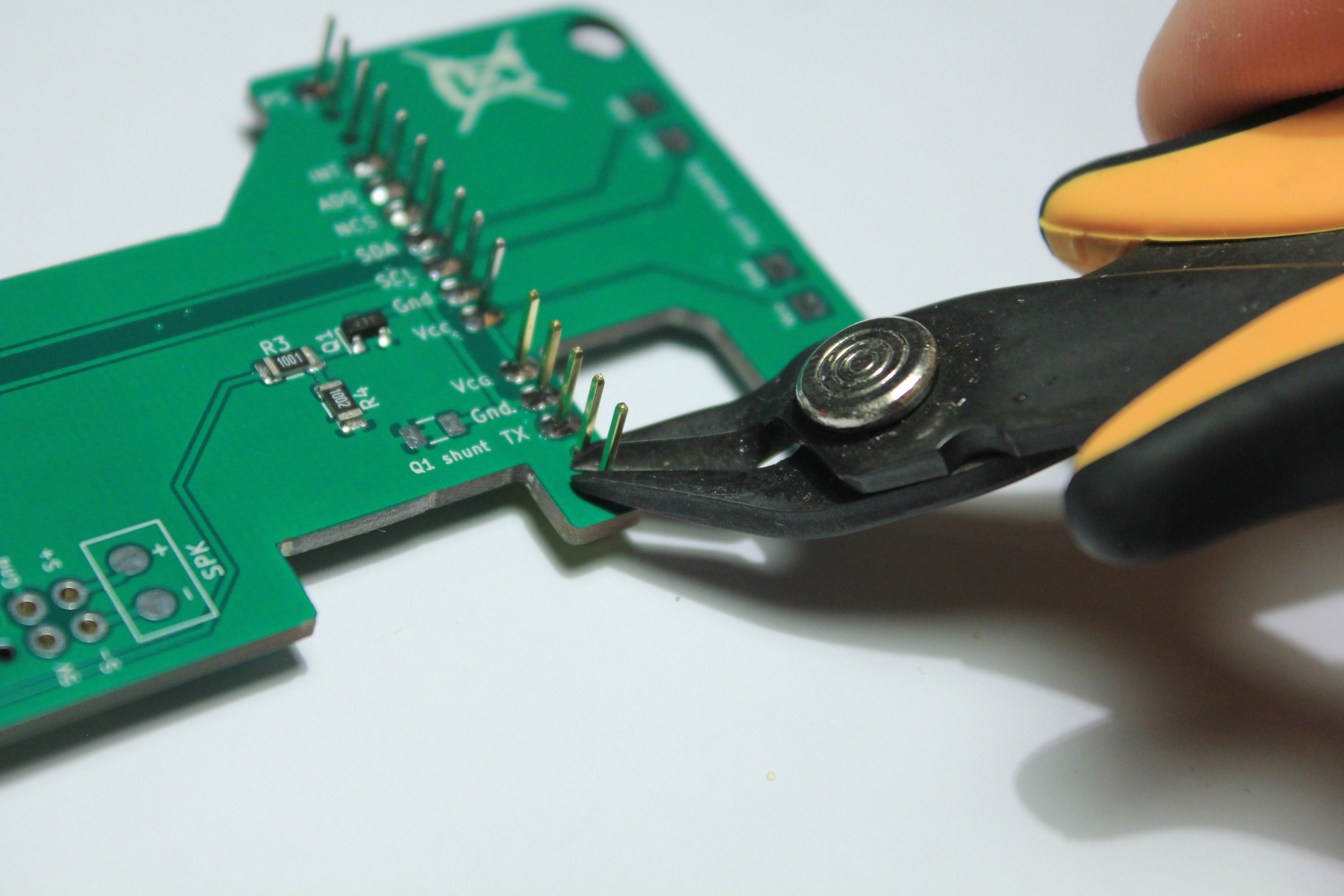
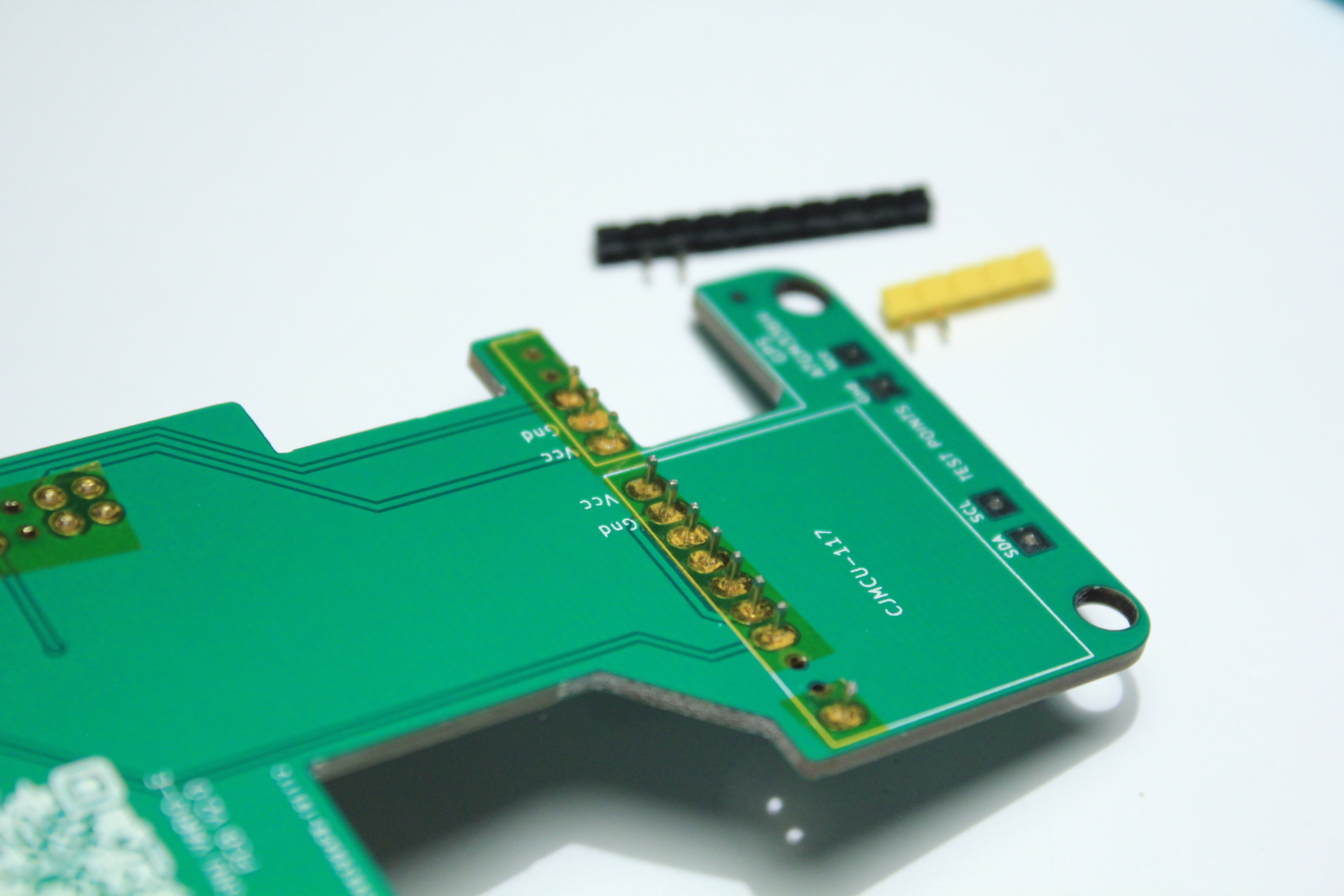
Cut the pins as close as possible to the welds.
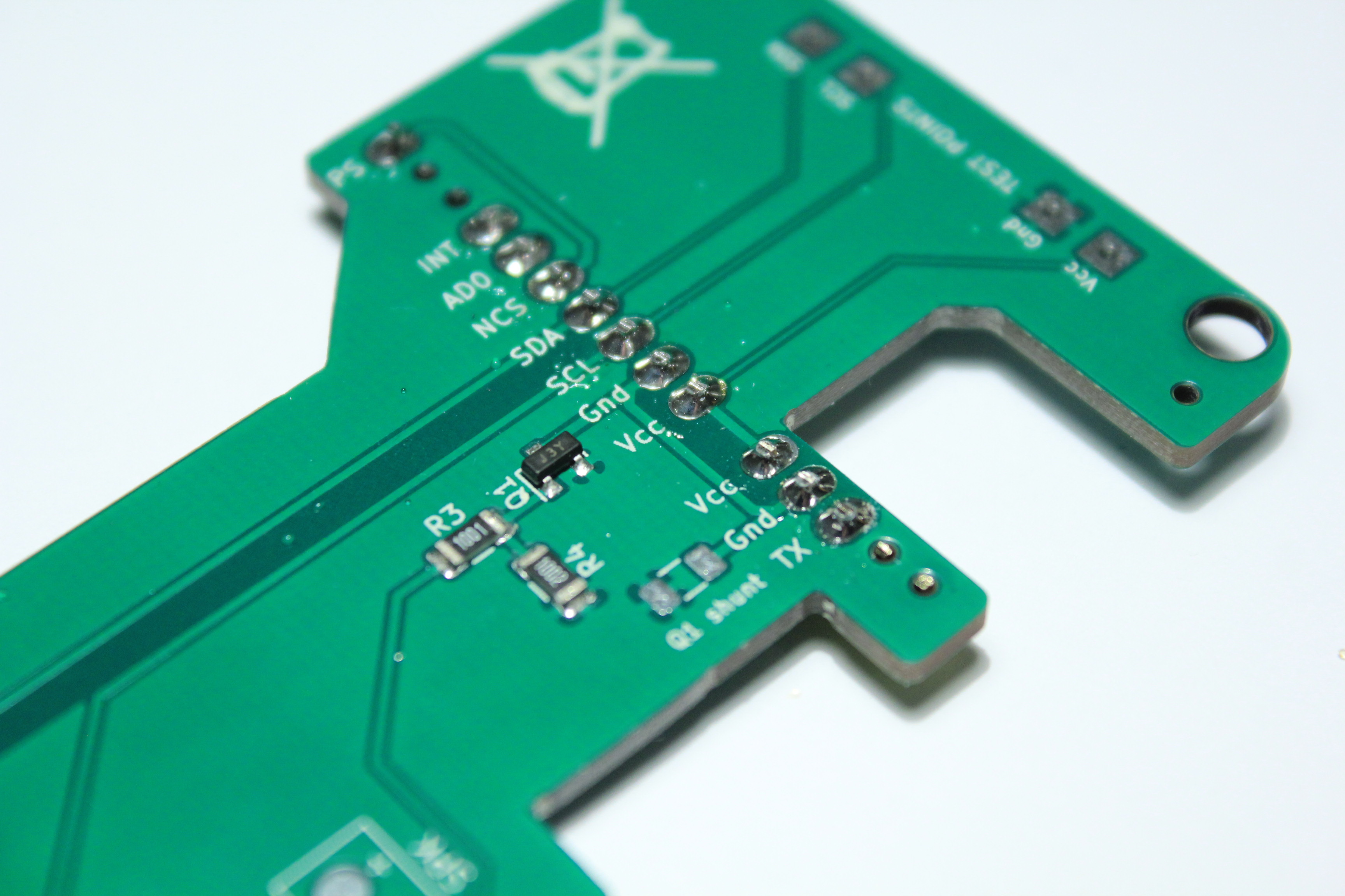
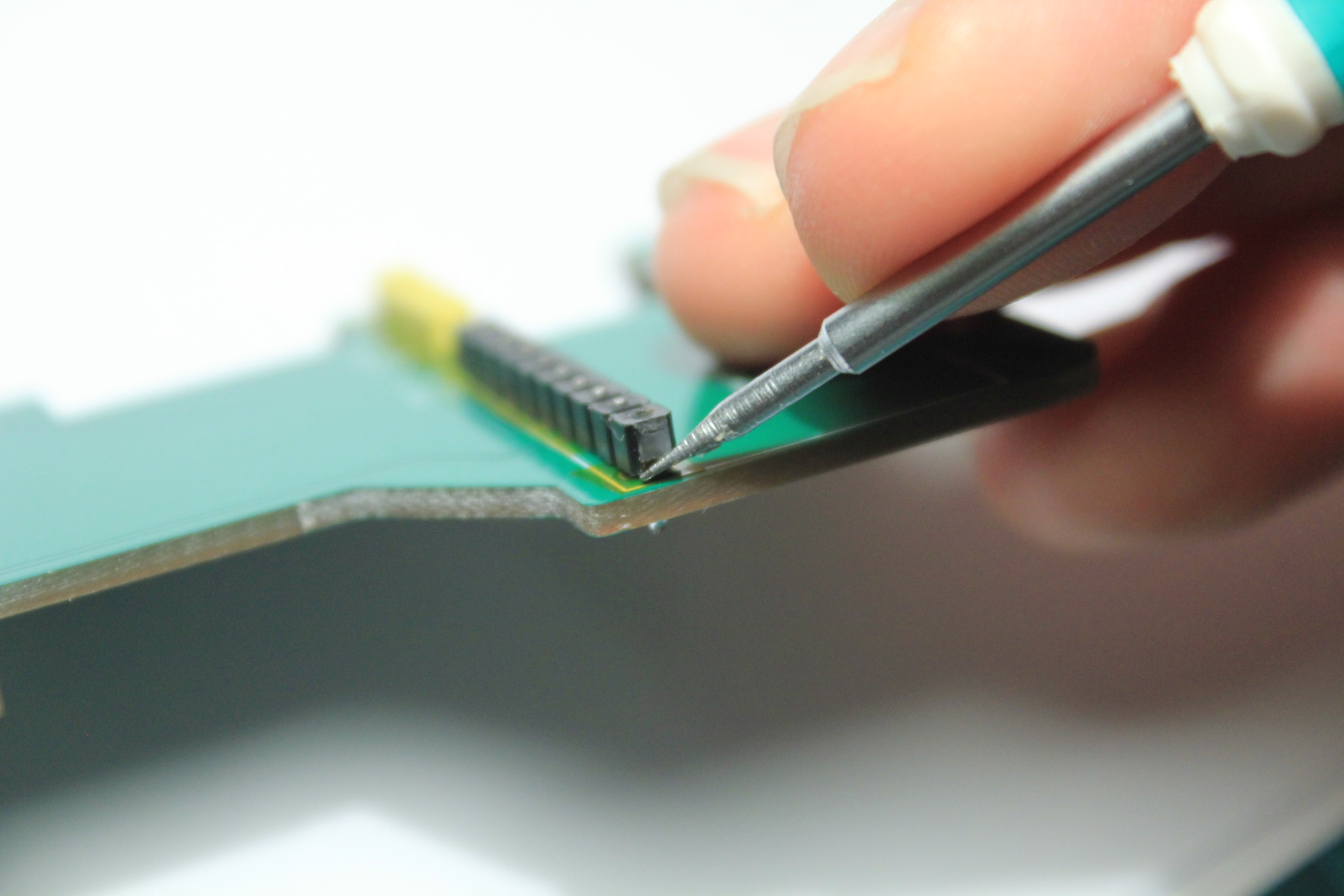
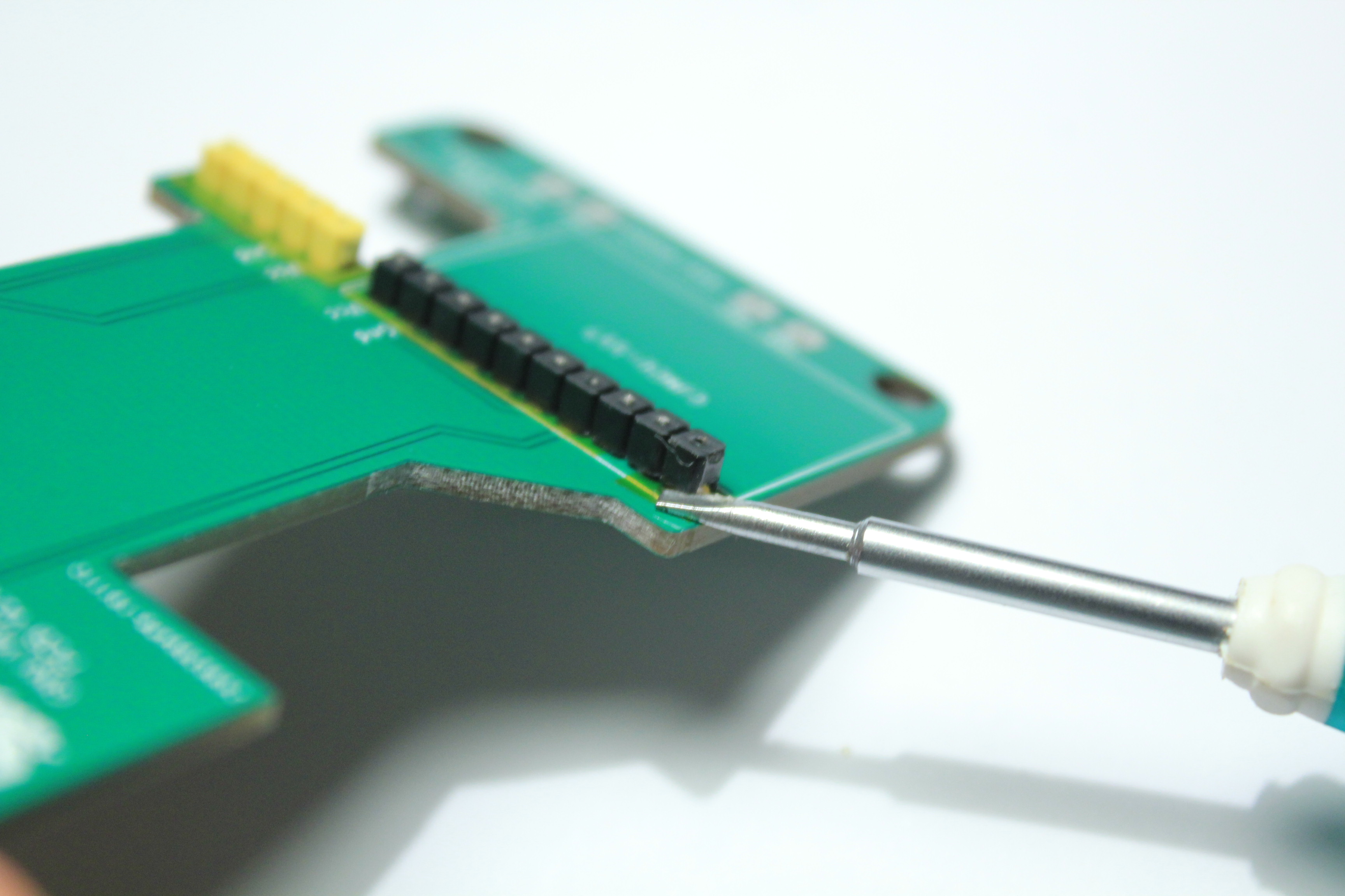
Remove the insulation using a thin screwdriver
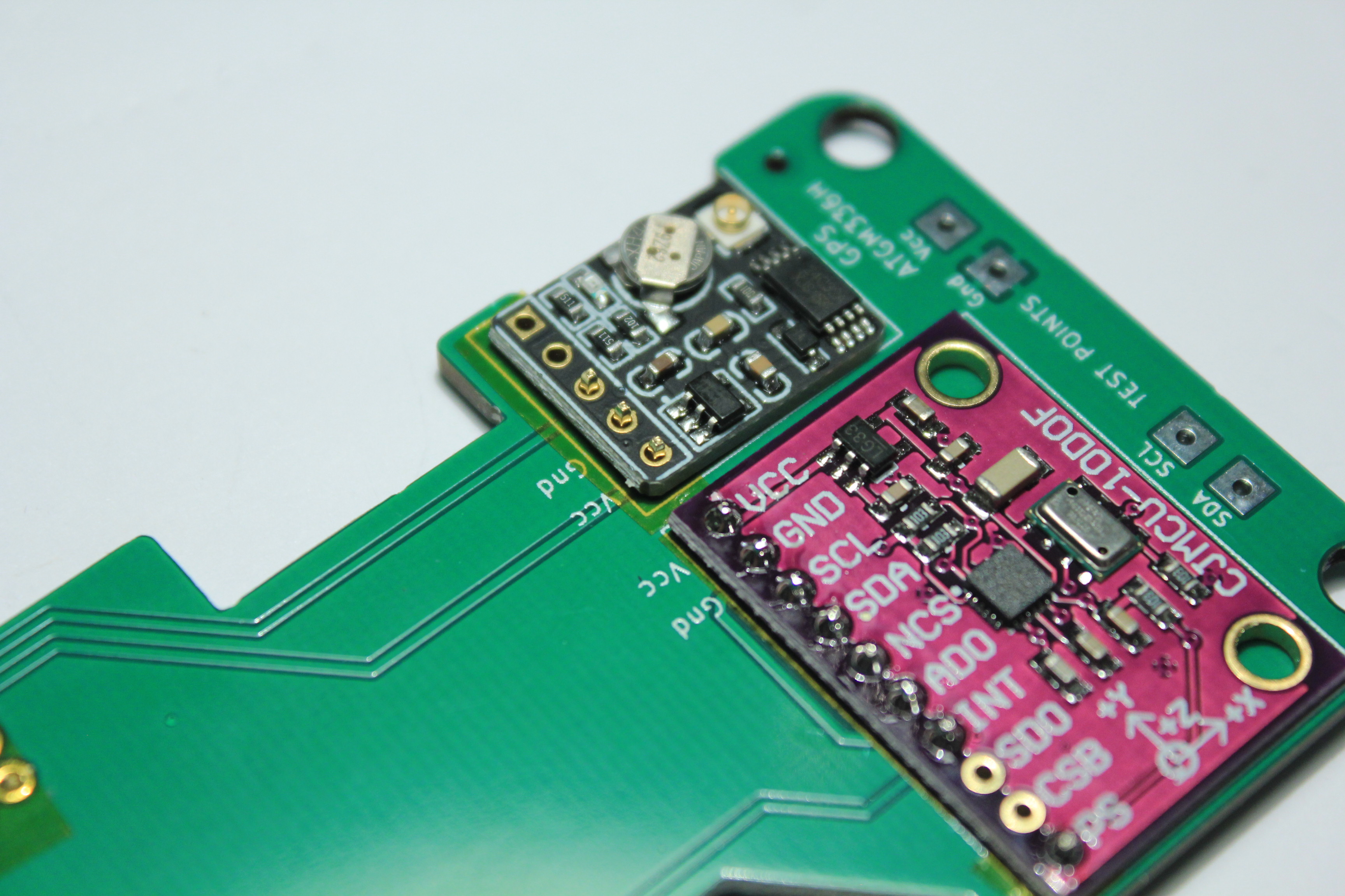
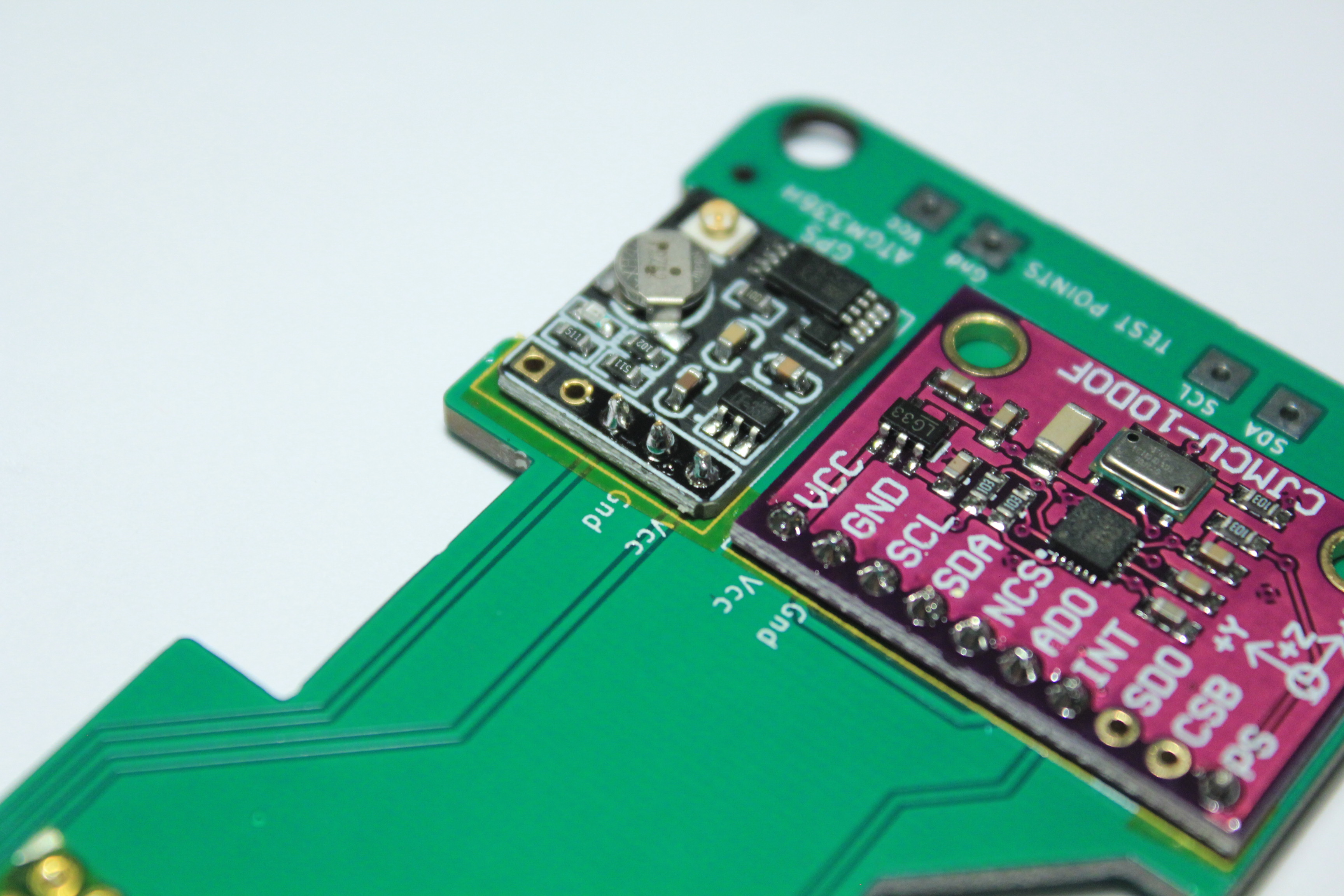
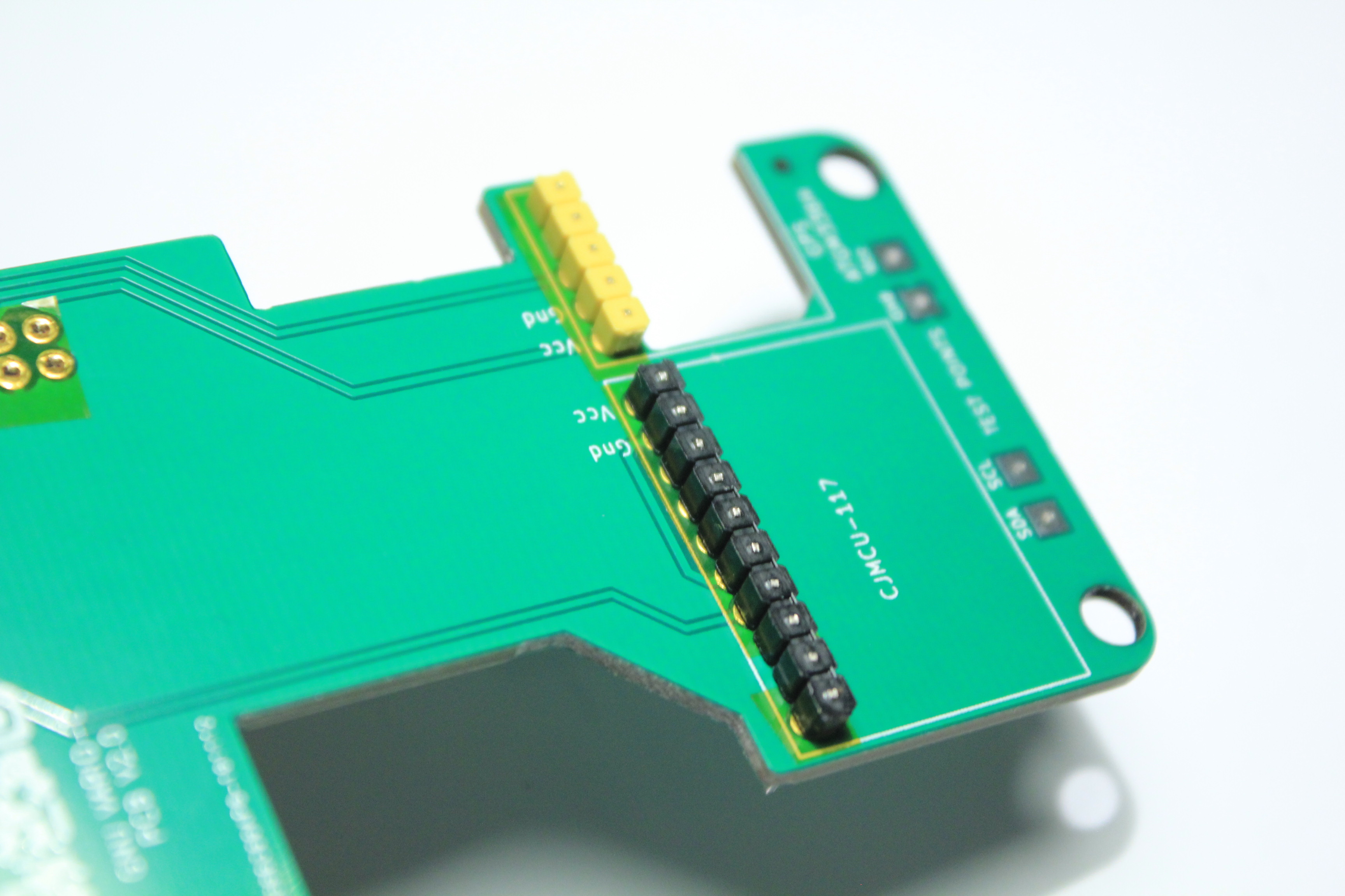
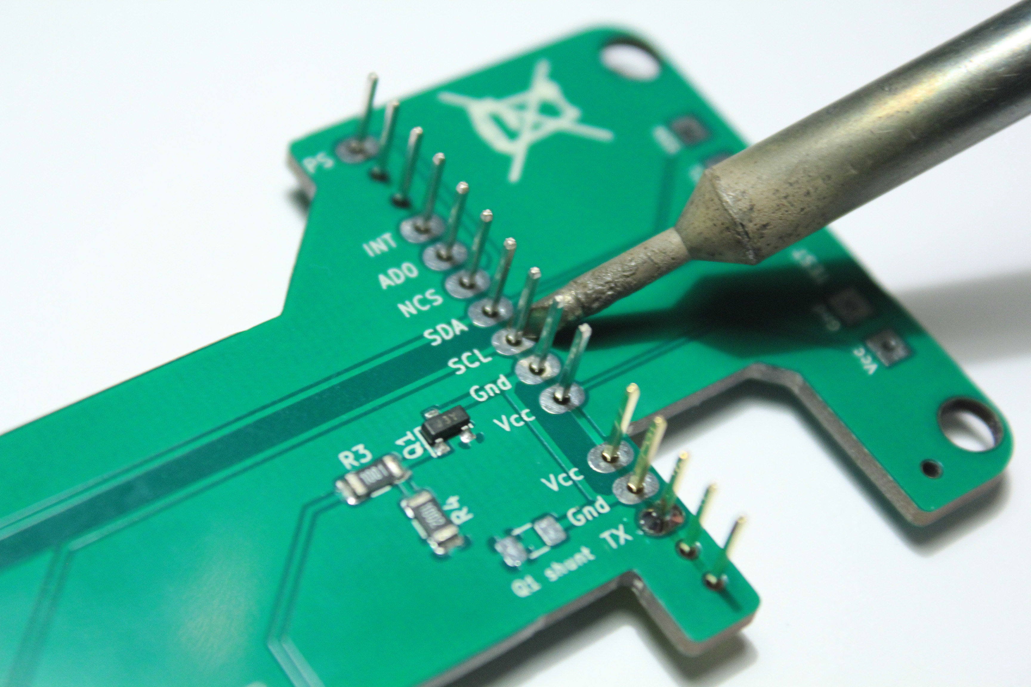
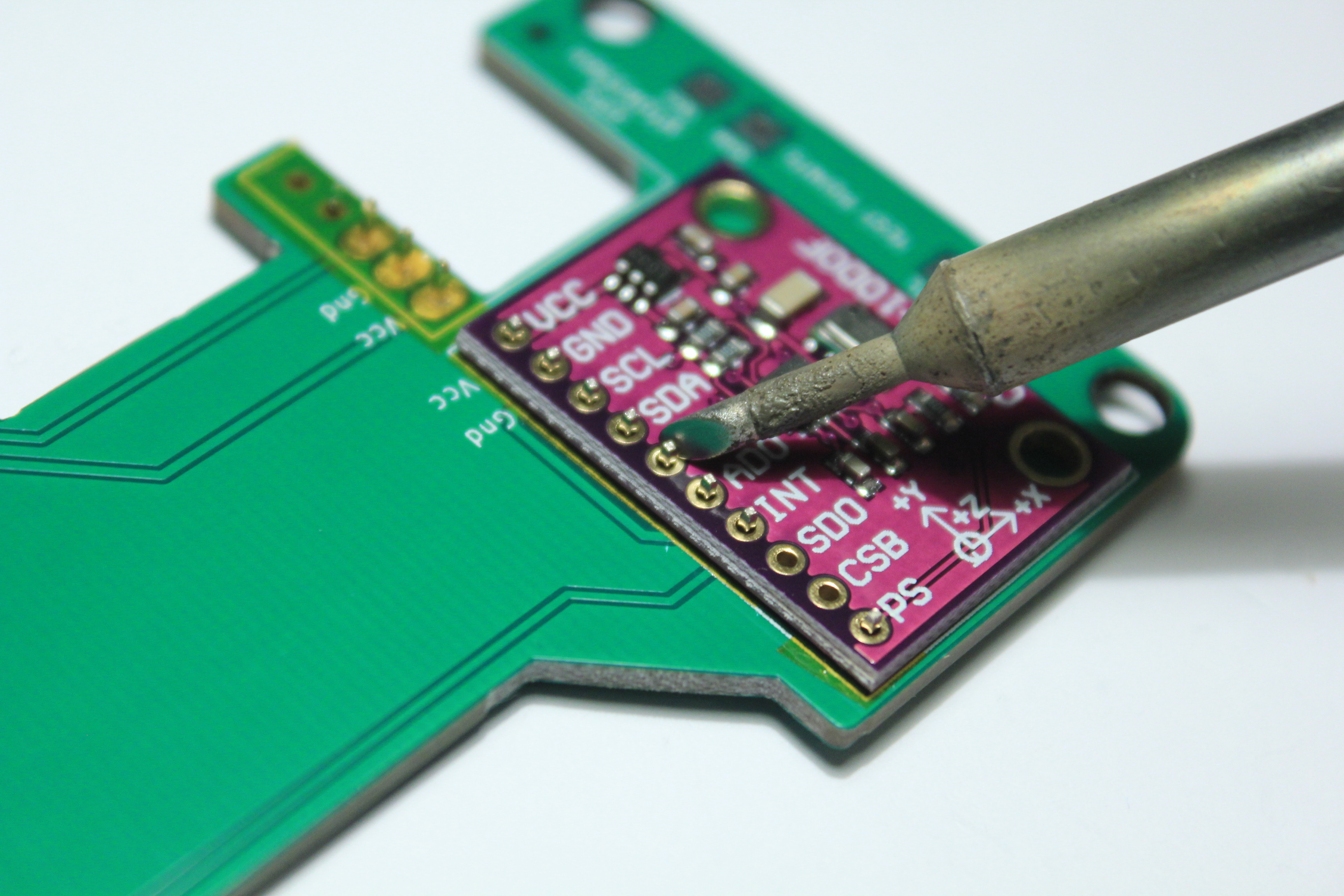
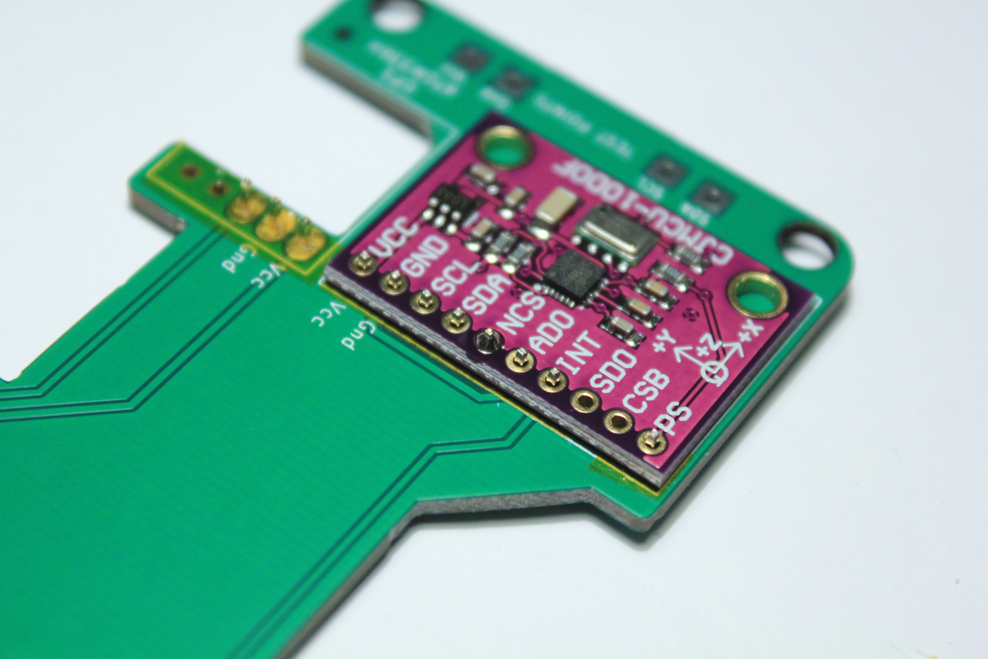
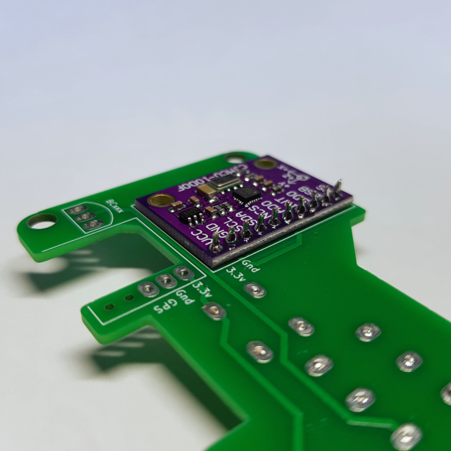
Then place the MPU against the PCB like this:
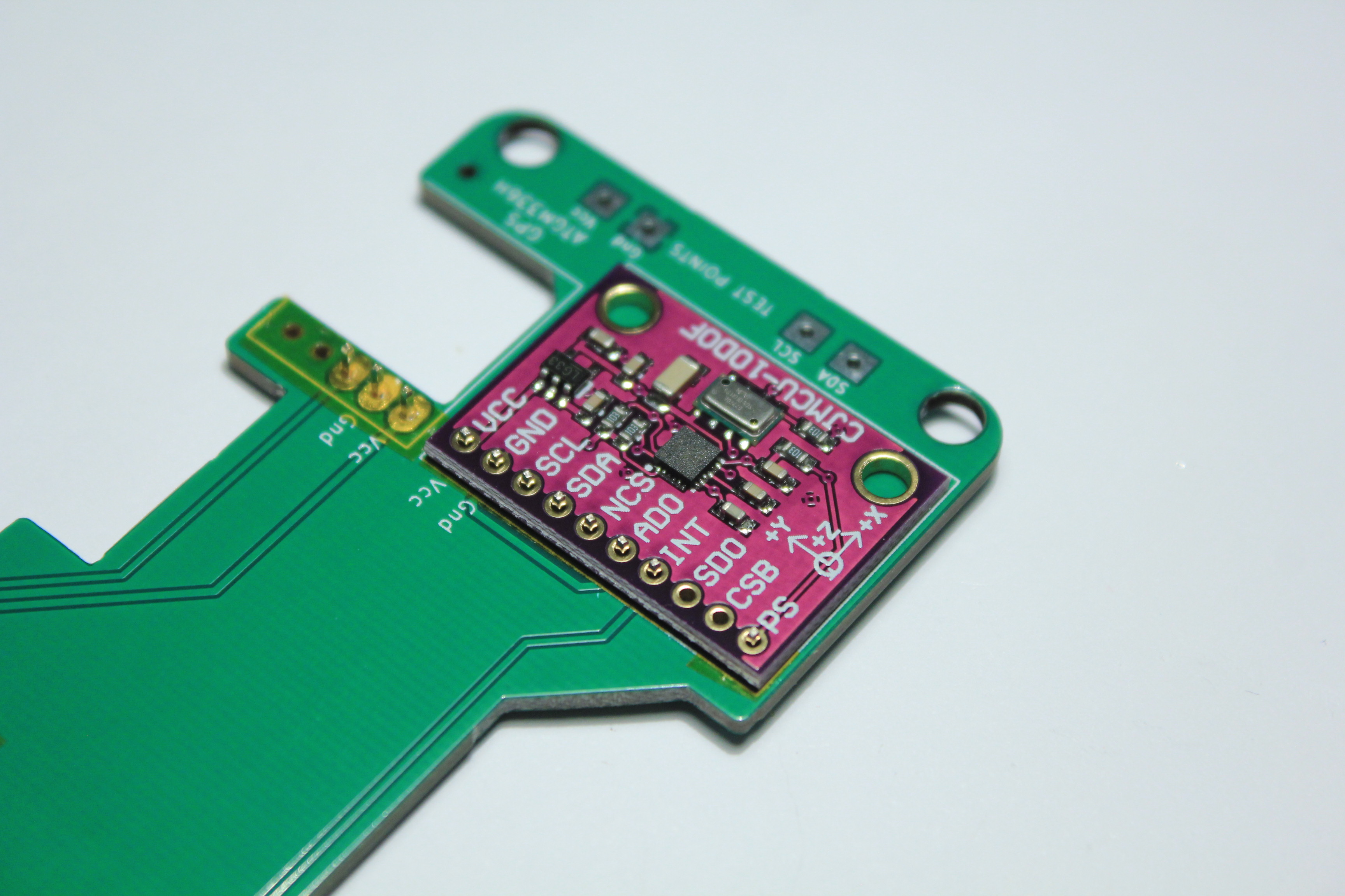
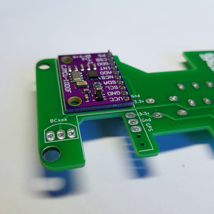
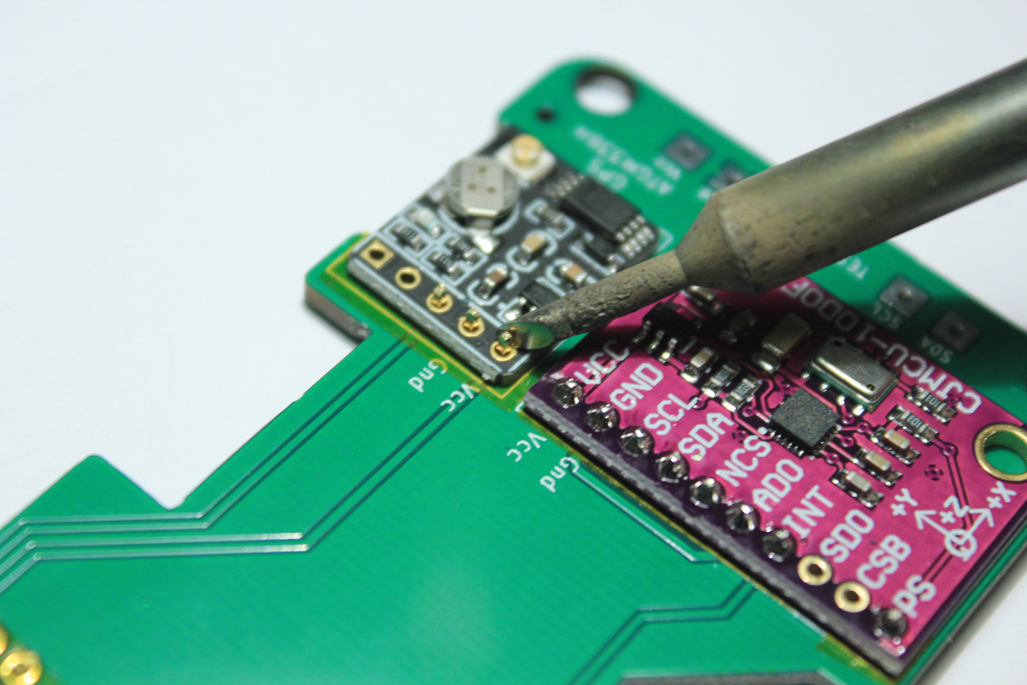
Make sure all the cards are flat on the circuit board. Solder only one pin of the card, check its location.
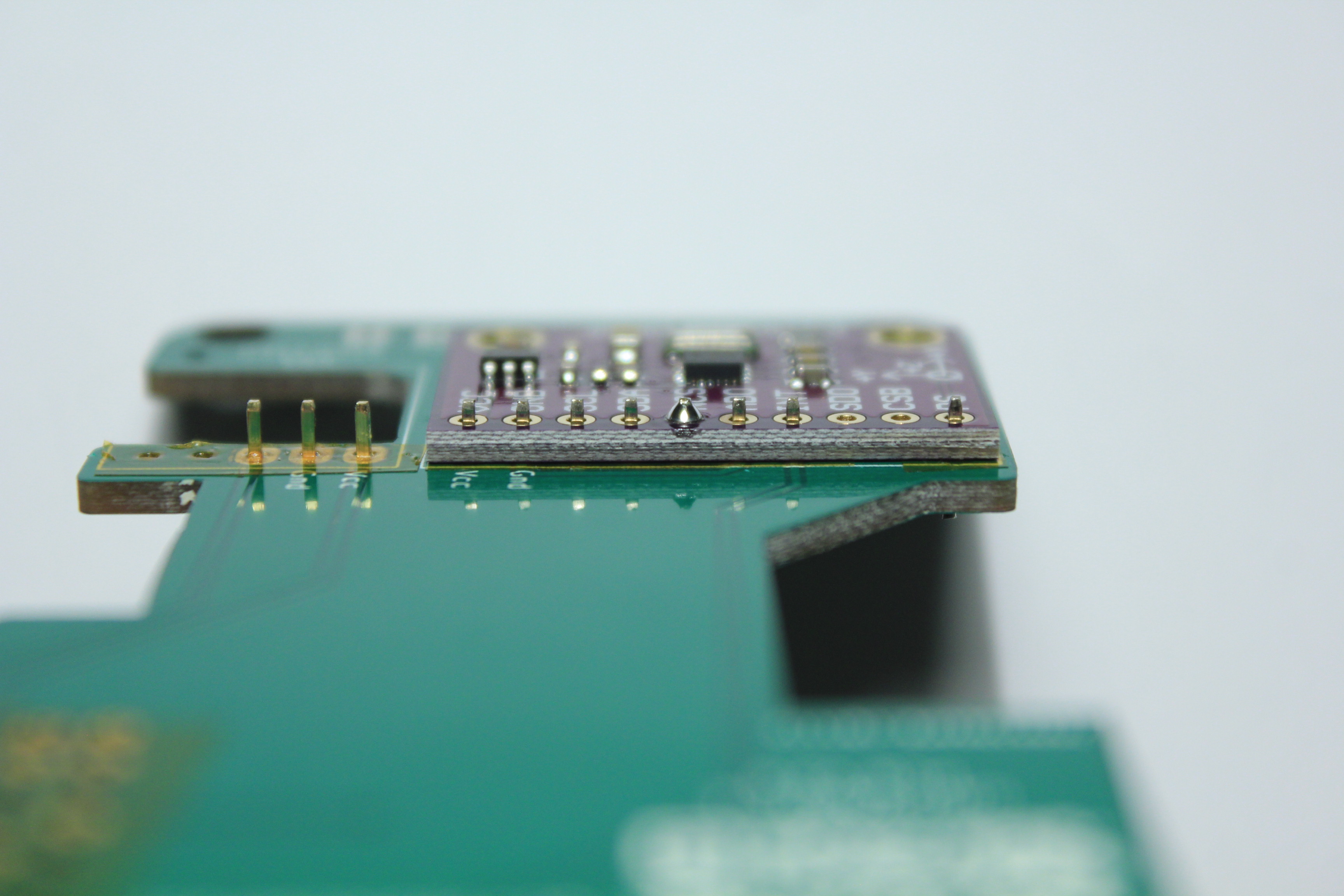
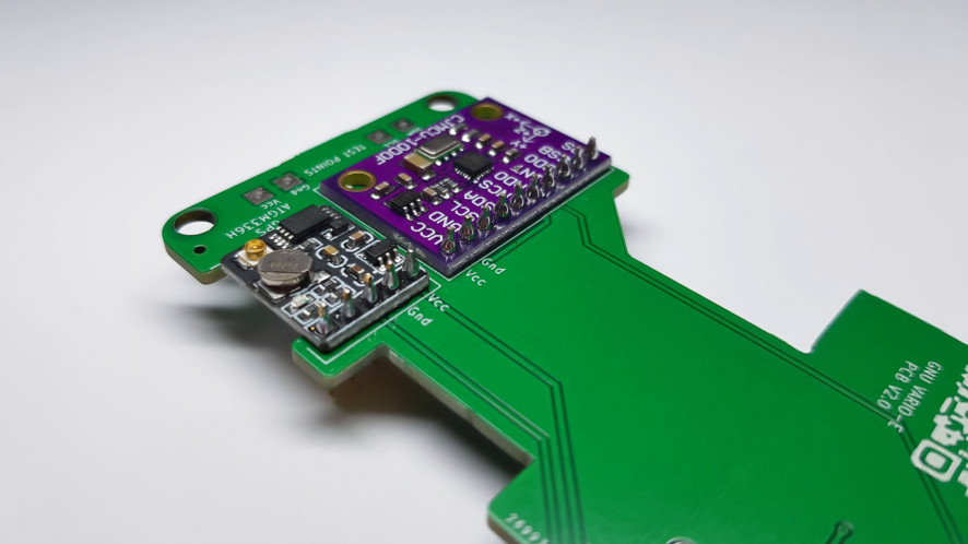
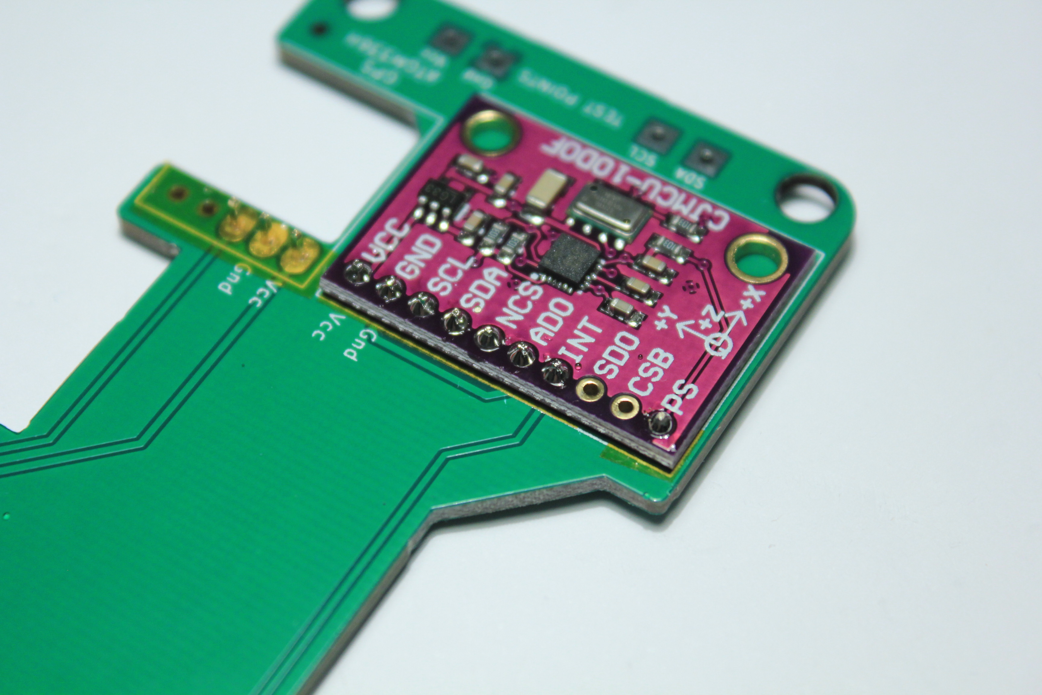
Solder the other pins. Be very careful! Don’t forget some of them.
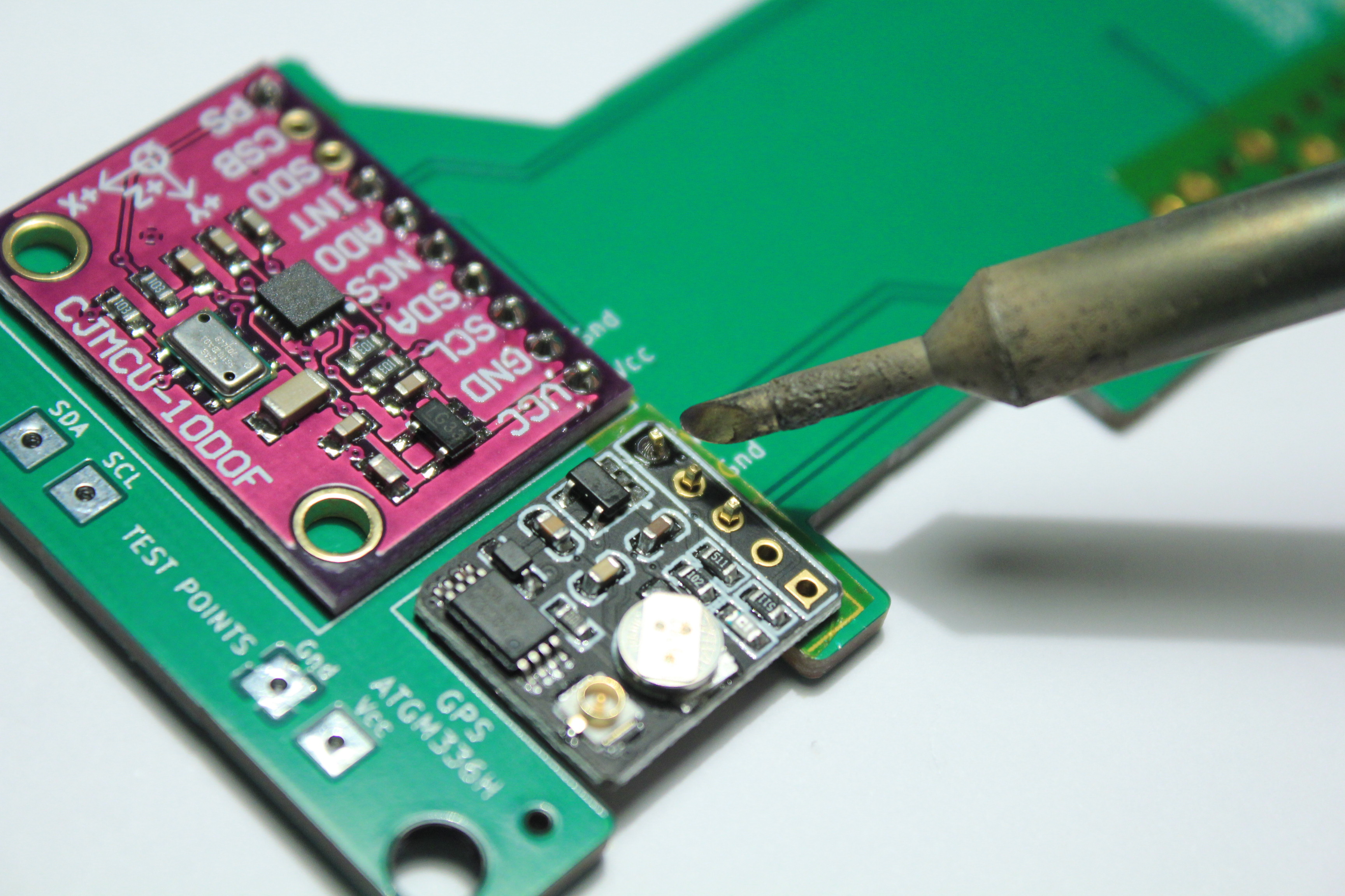
Repeat with the GPS