Hardware
Building tutorial summary
Connectors soldering
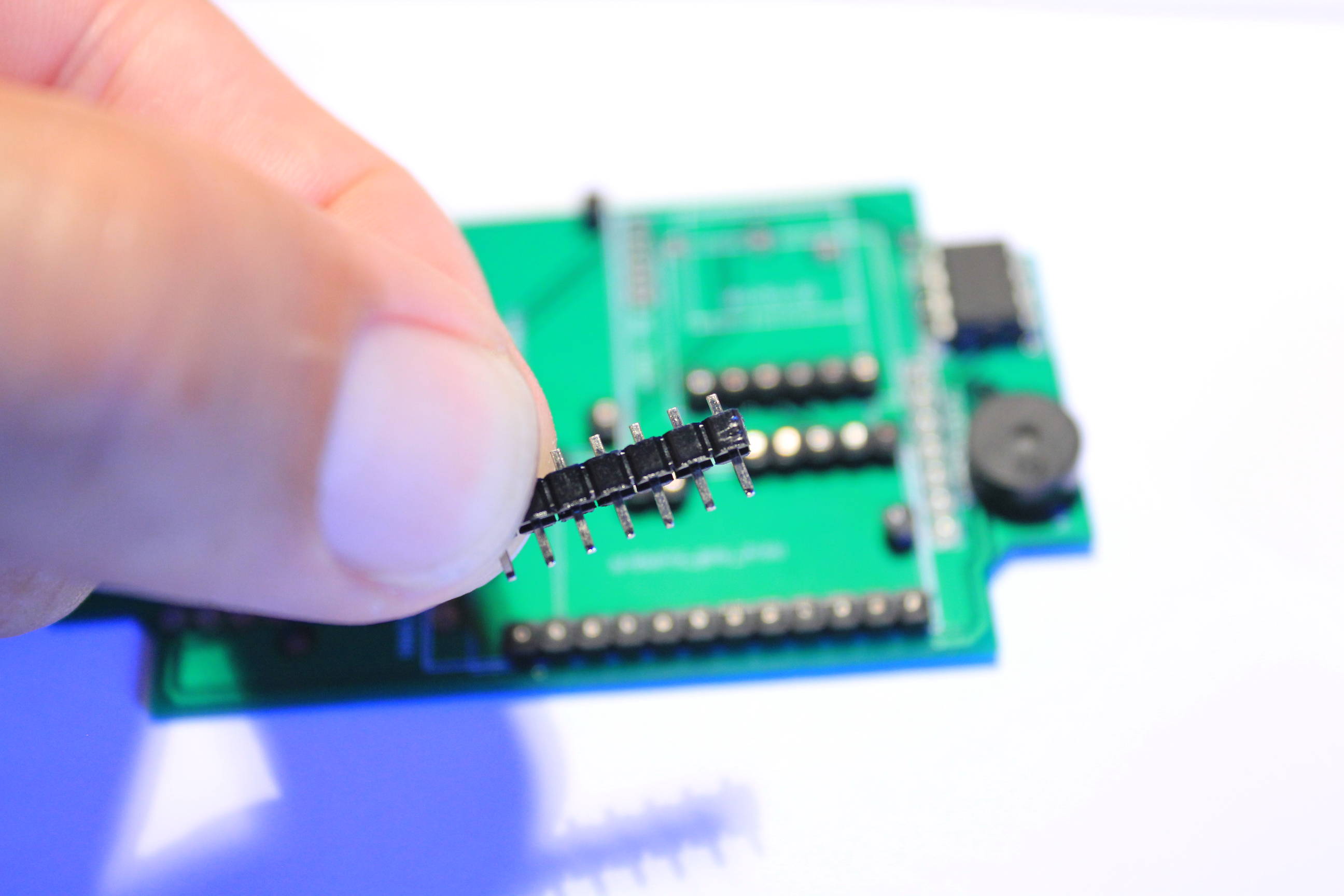
This step is a little more difficult because we need to solder some pin headers with long heads.
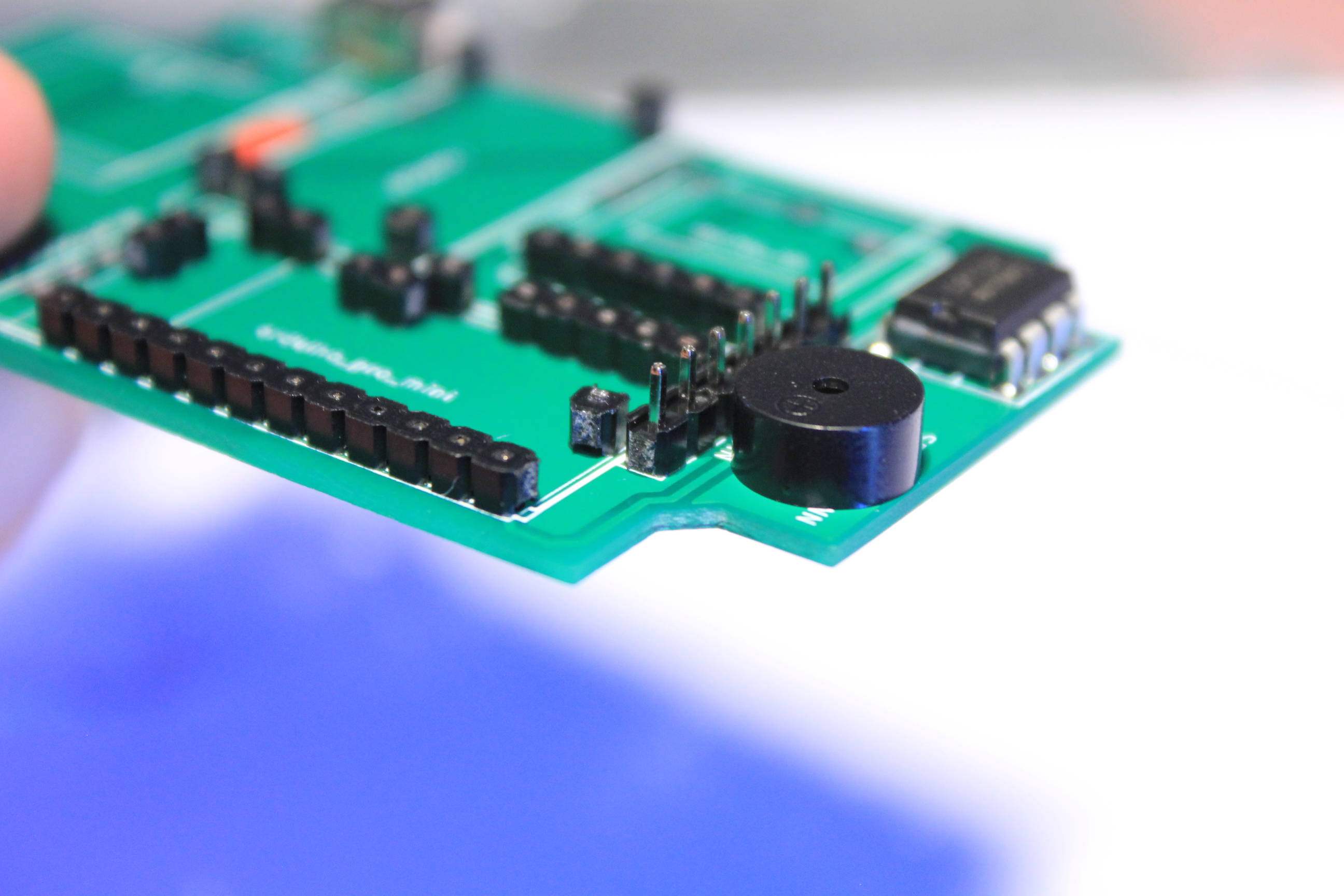
Take the pin headers with the smallest heads and with the legs close to the PCB thickness.
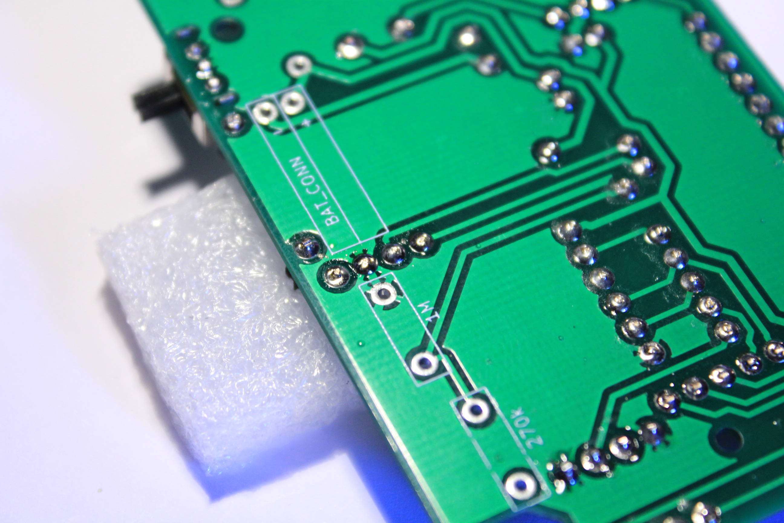
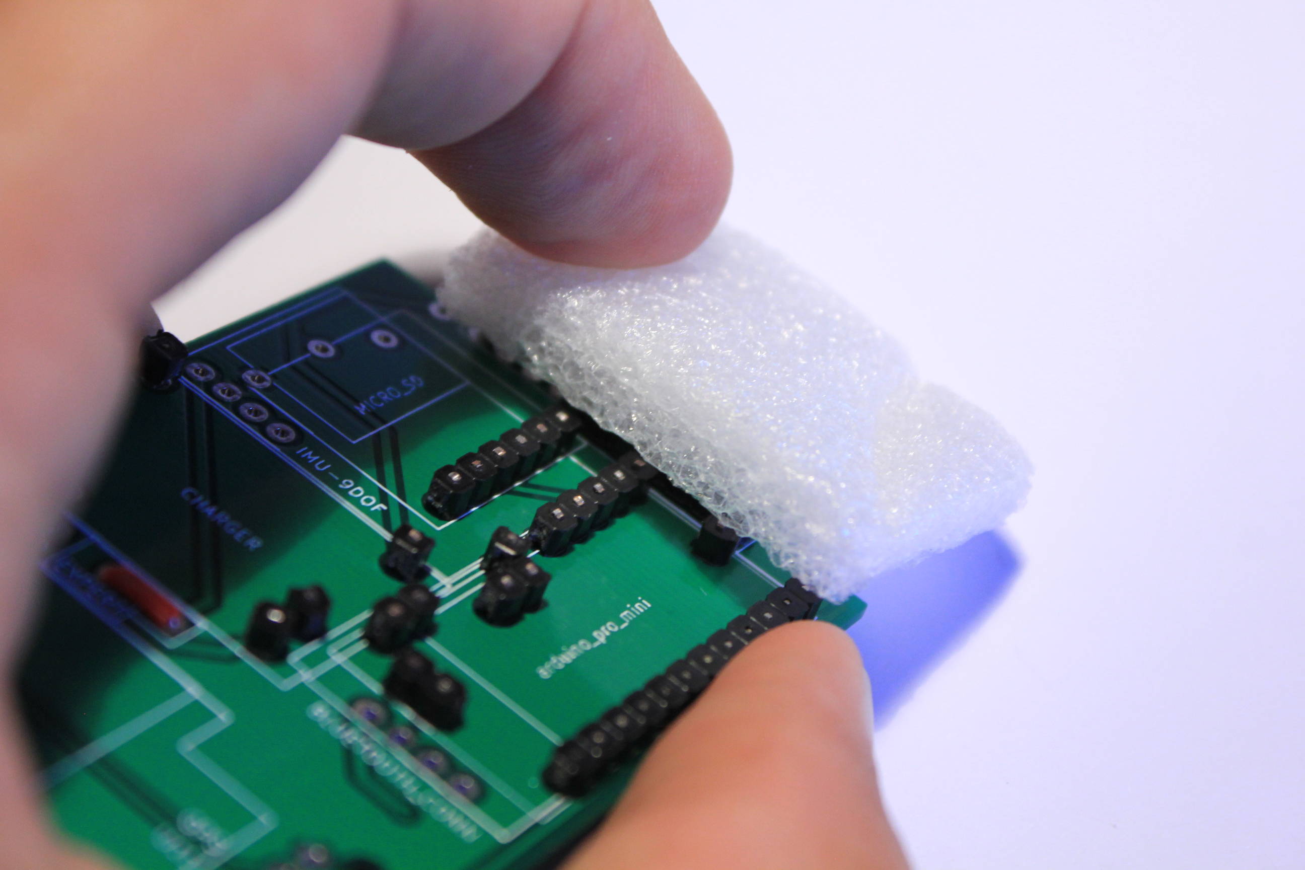
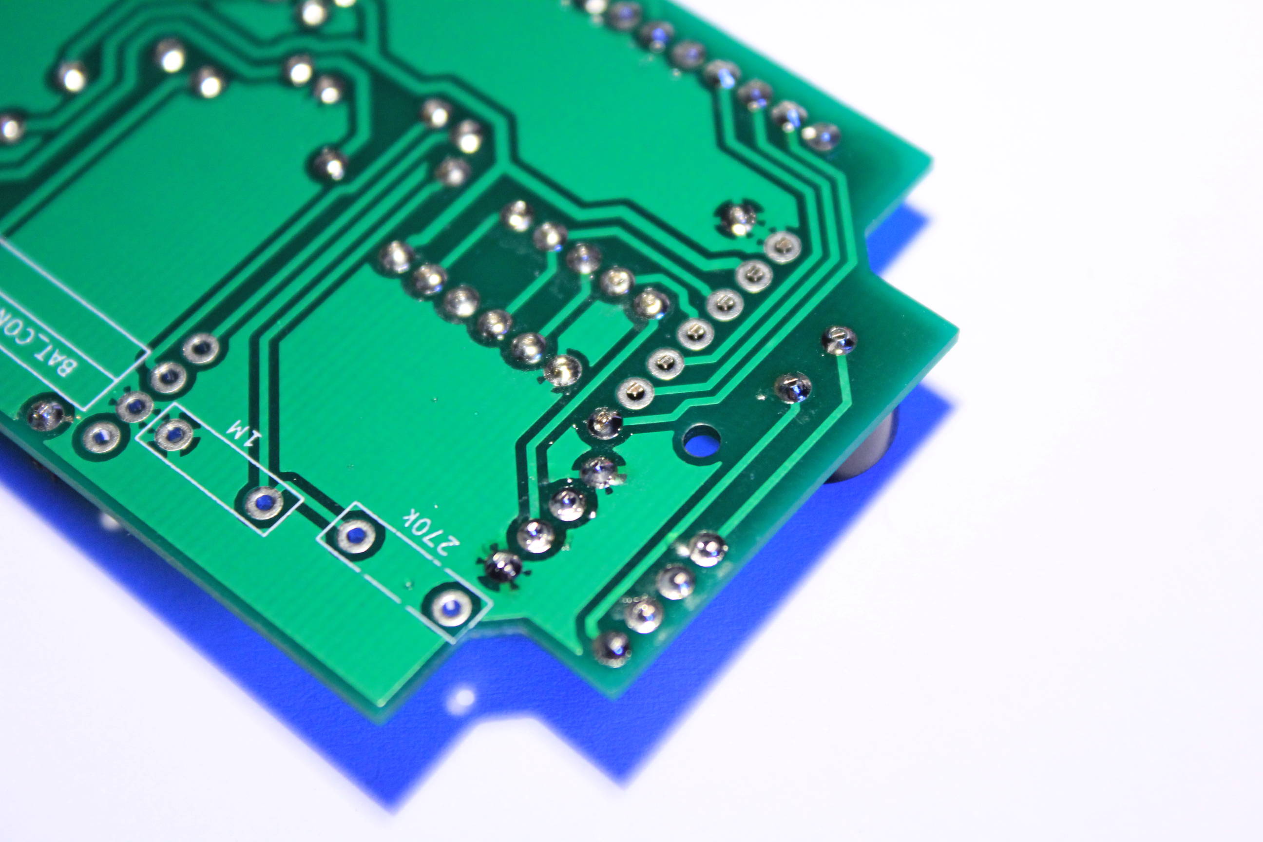
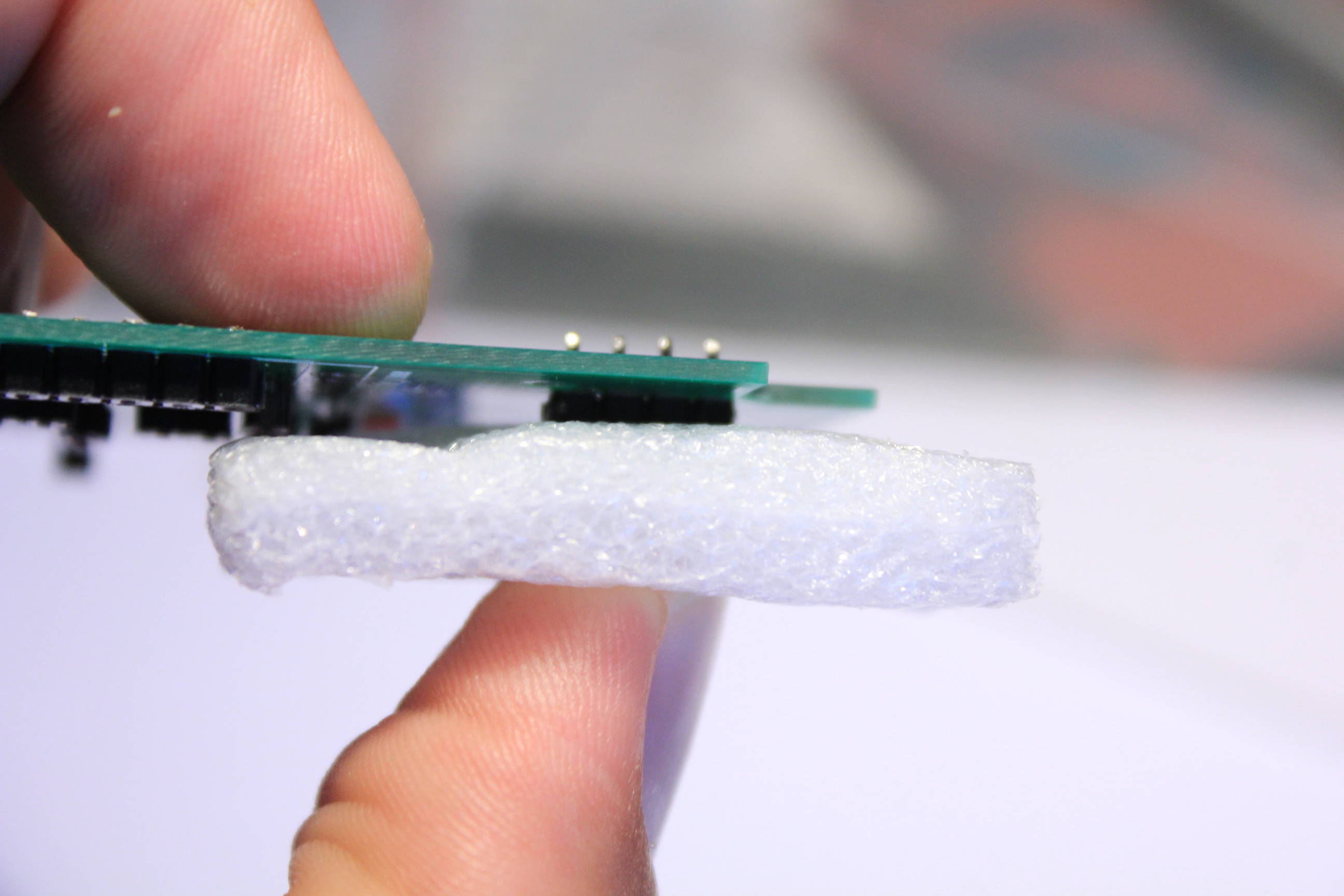
Put them on the screen connector and return the PCB using a small piece of foam.
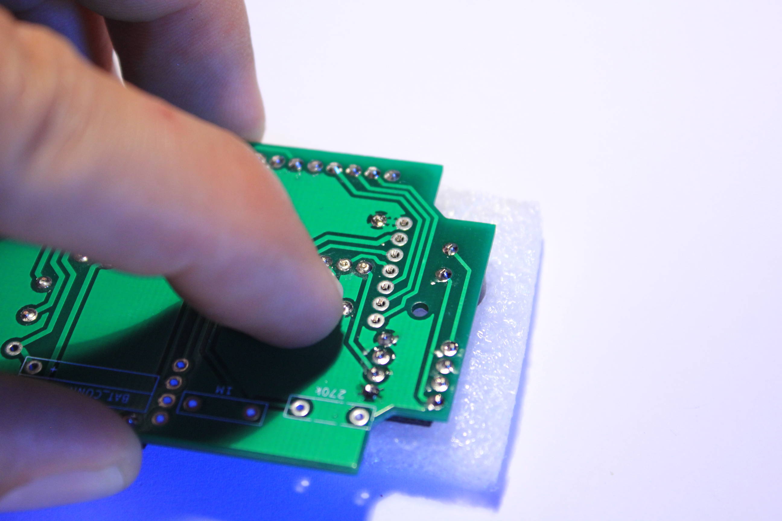
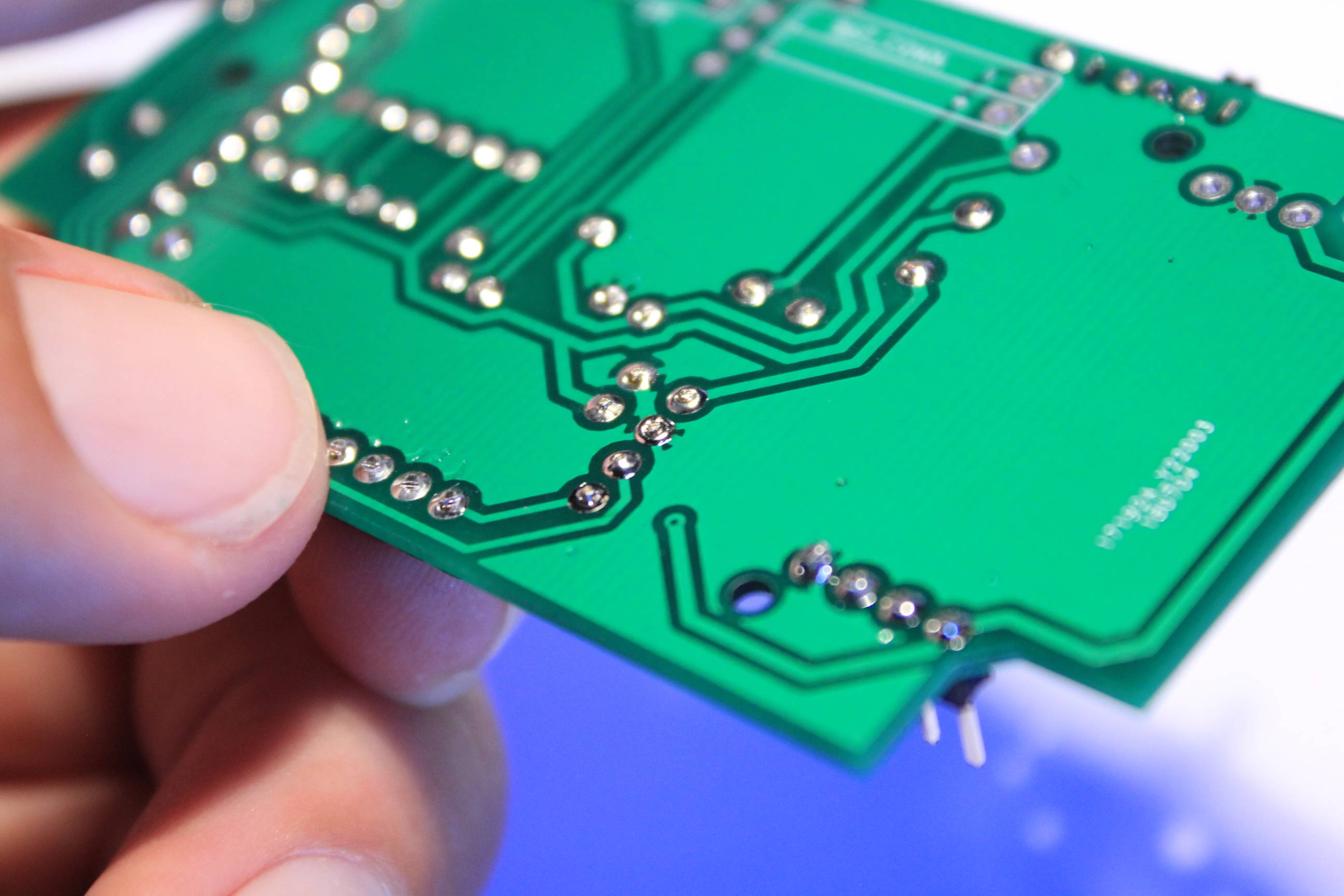
Solder just one pin and check carrefully the pin headers verticality before soldering the other pins.
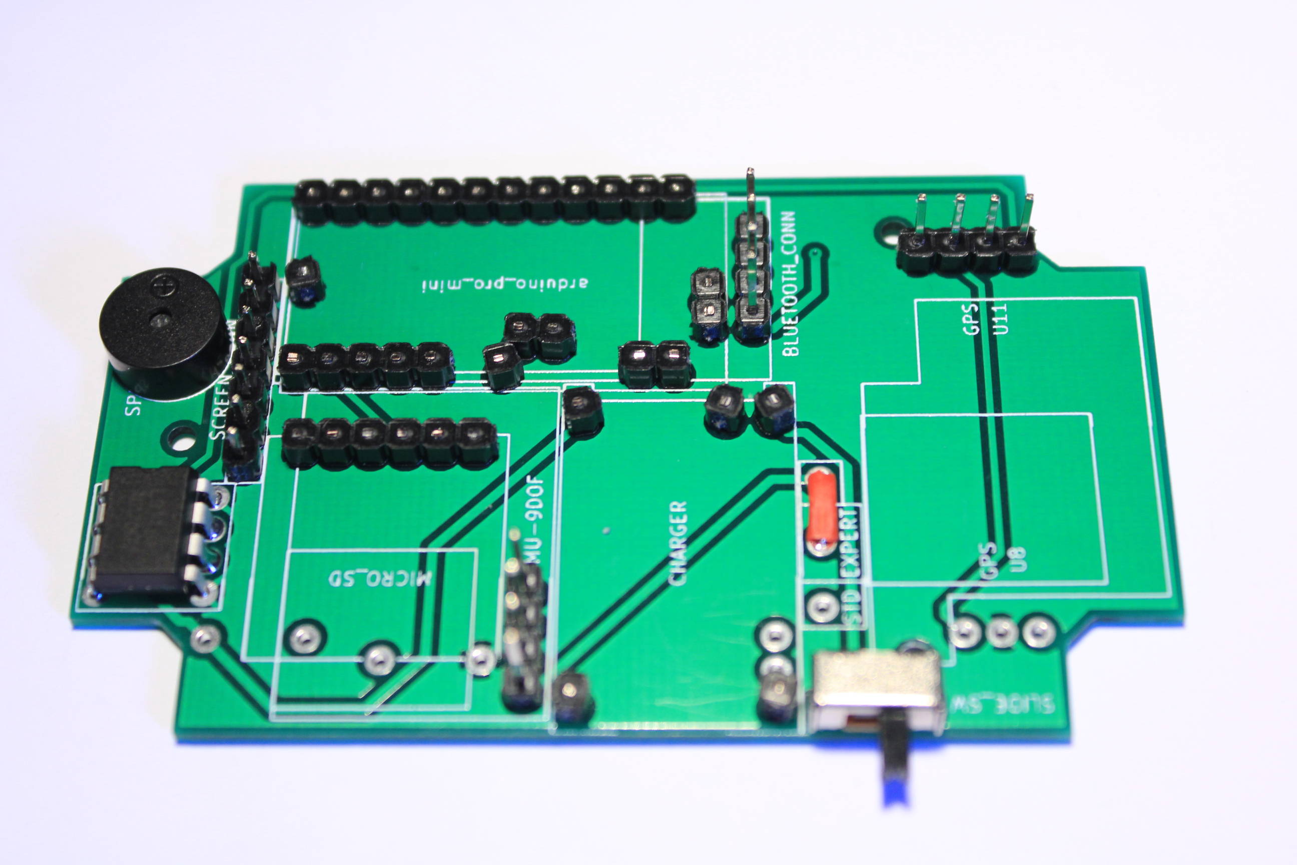
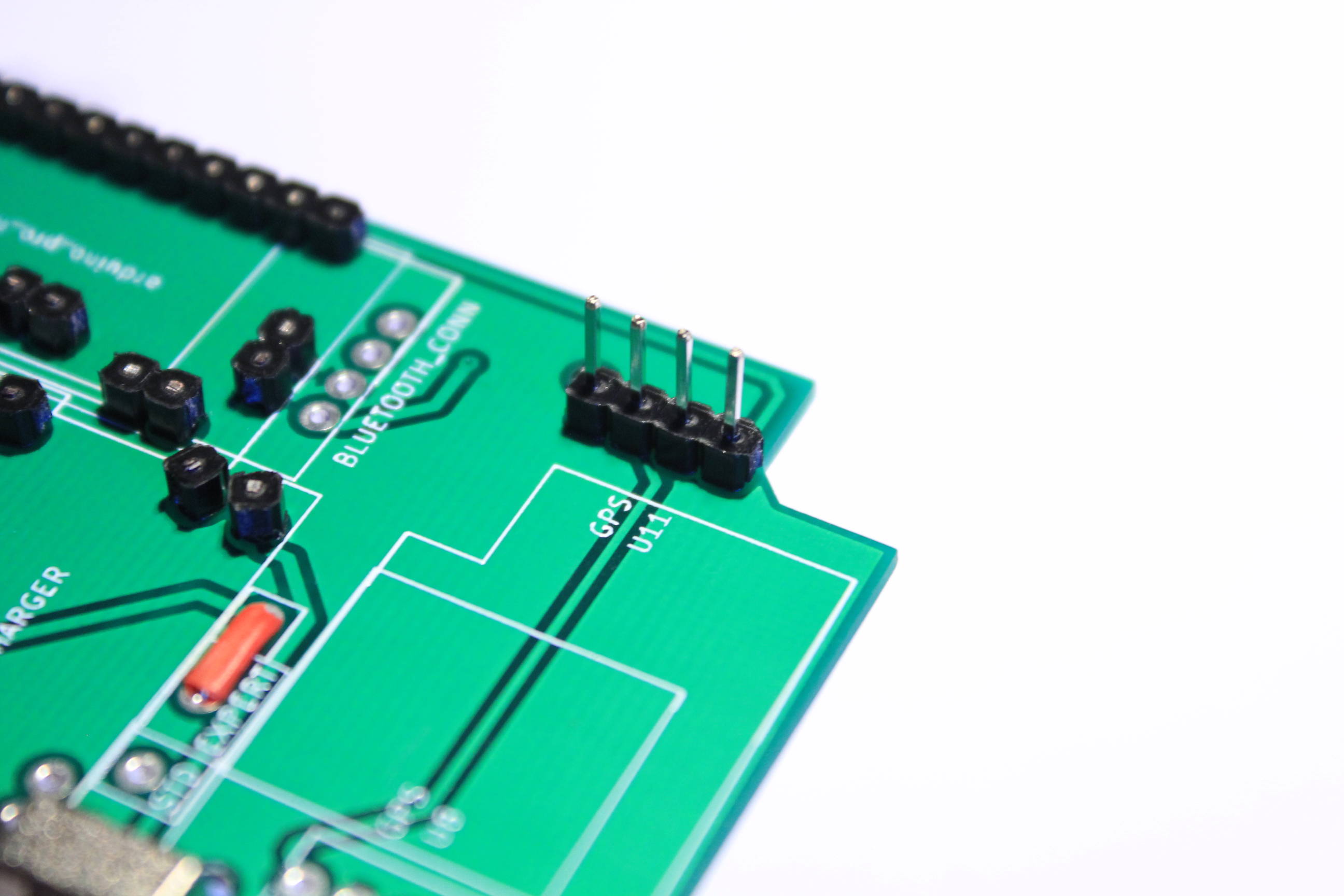
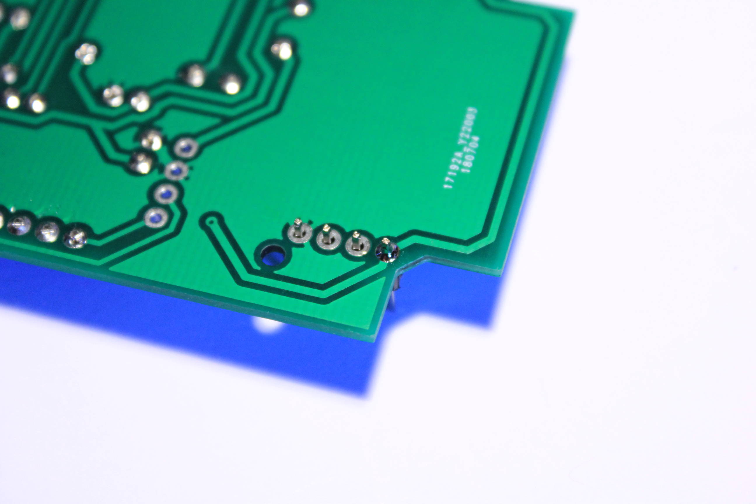
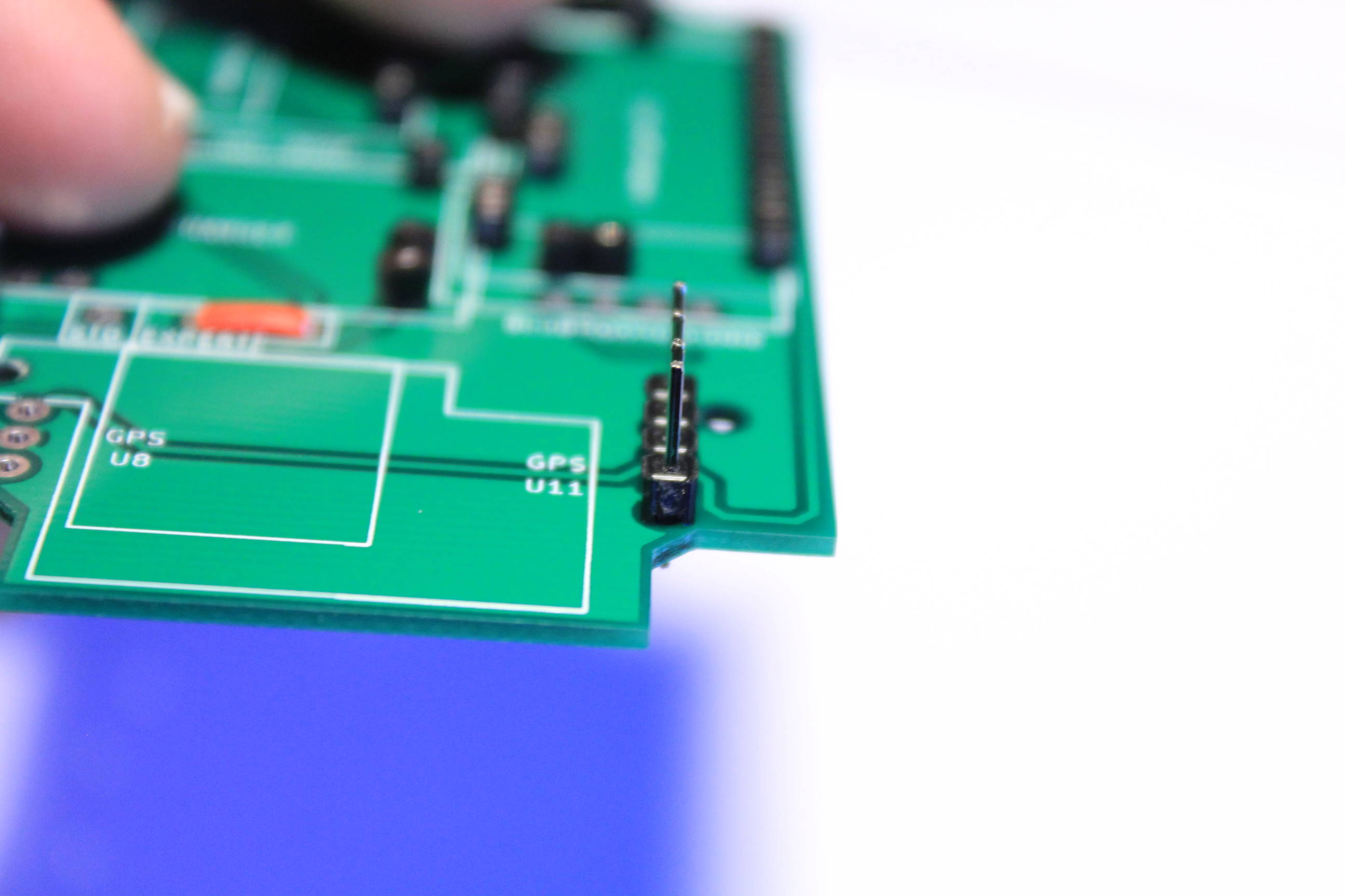
As we are not over the battery we can now take the standard pin headers for the GPS connector. Again check very carefully the headers verticality.
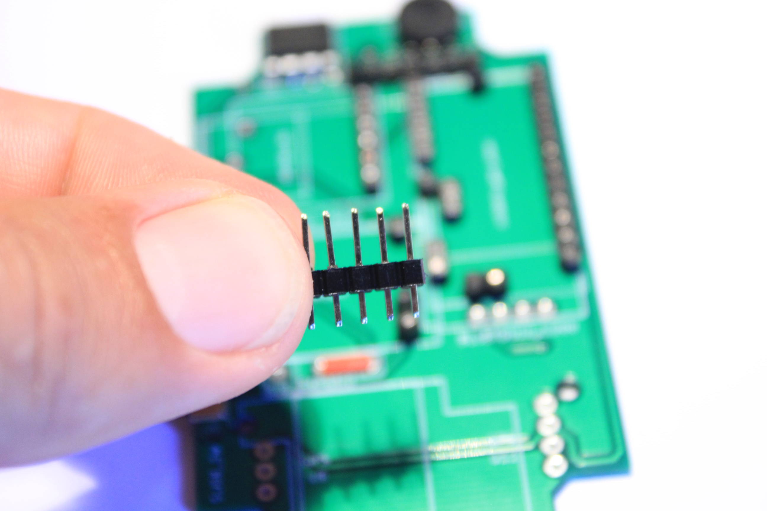
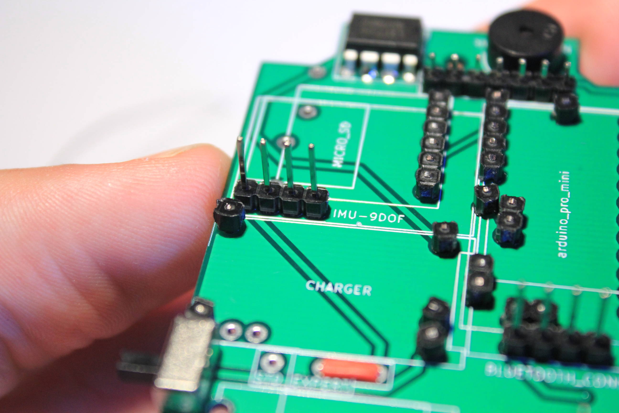
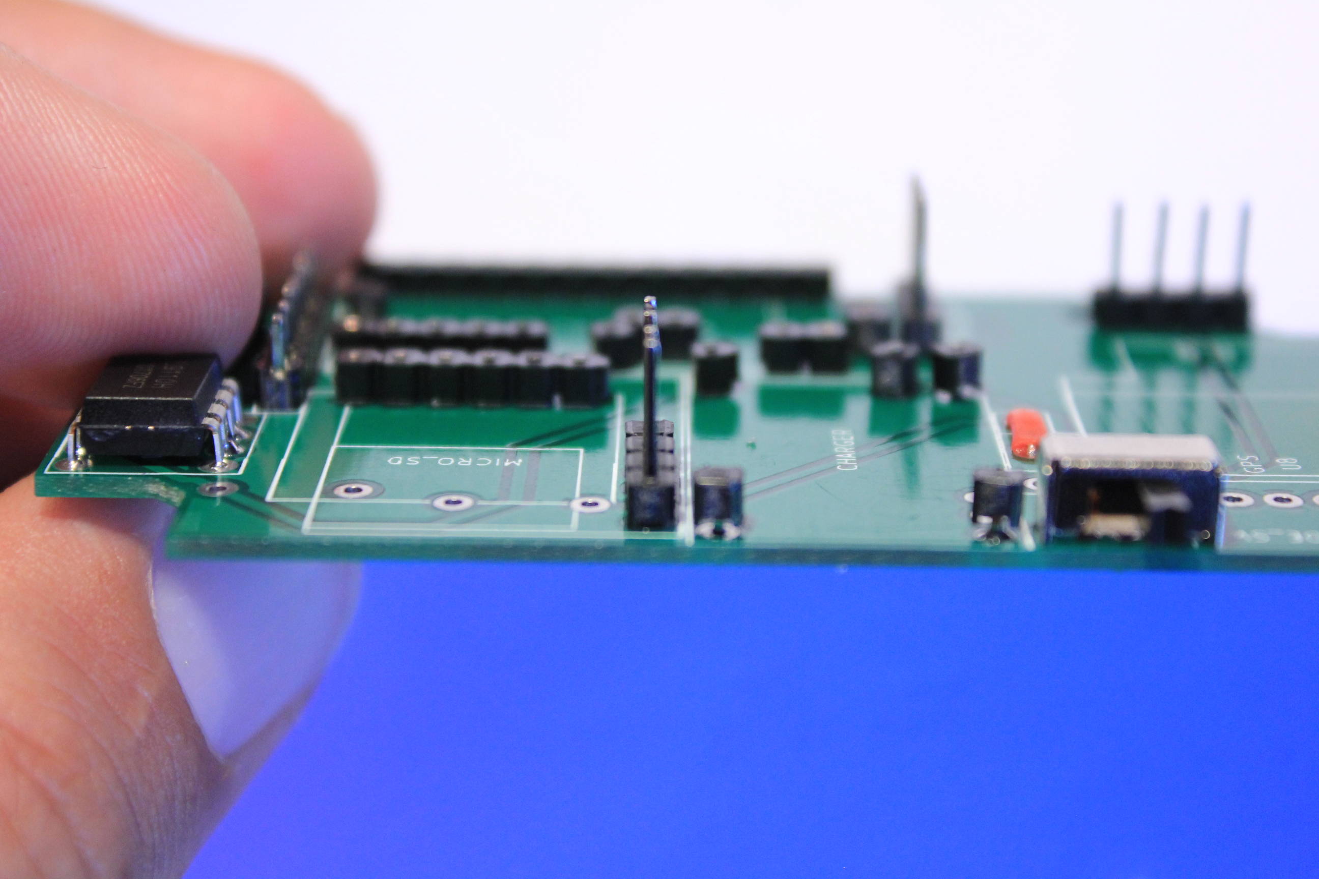
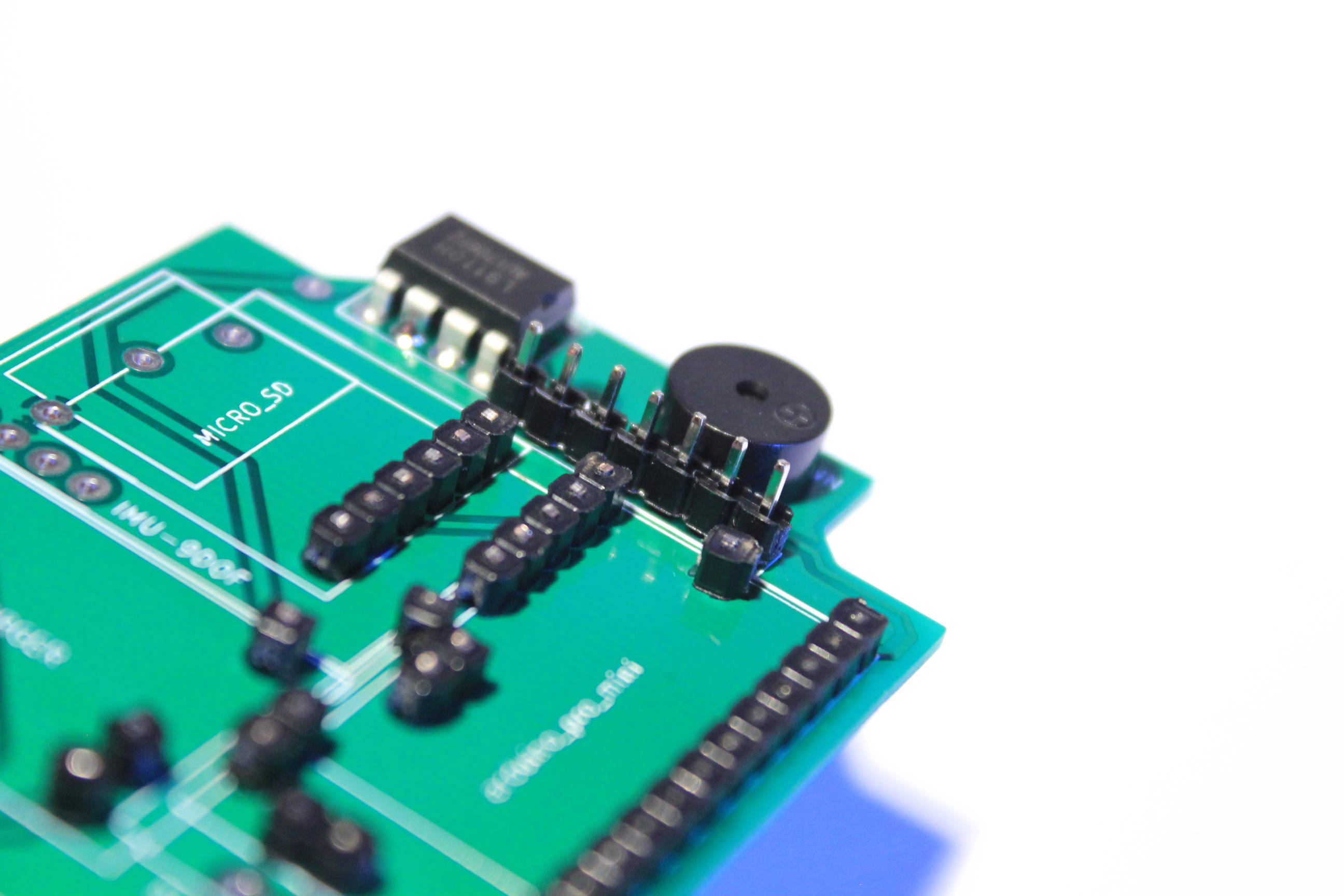
Now take the pin headers with very long heads and with legs close to the PCB thickness.
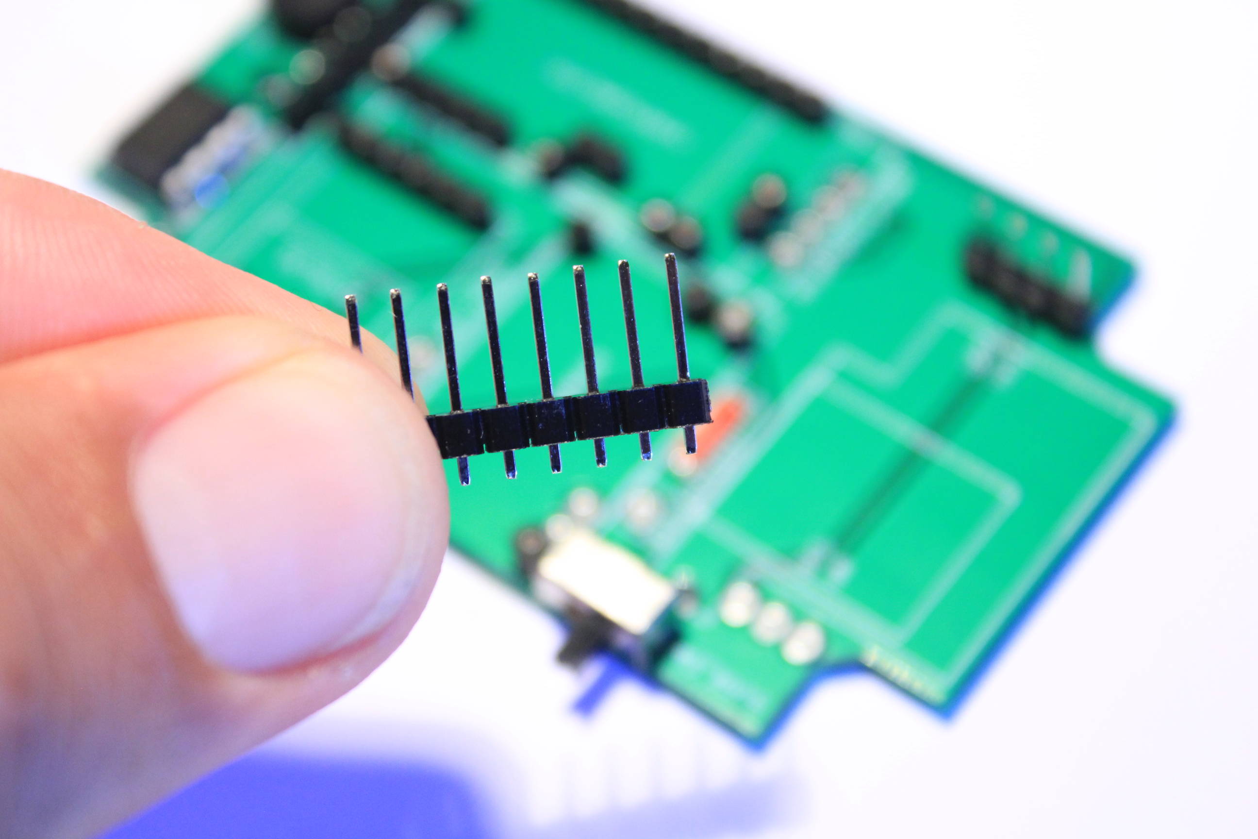
Use four pins for the bluetooth connector. Make flat soldering.
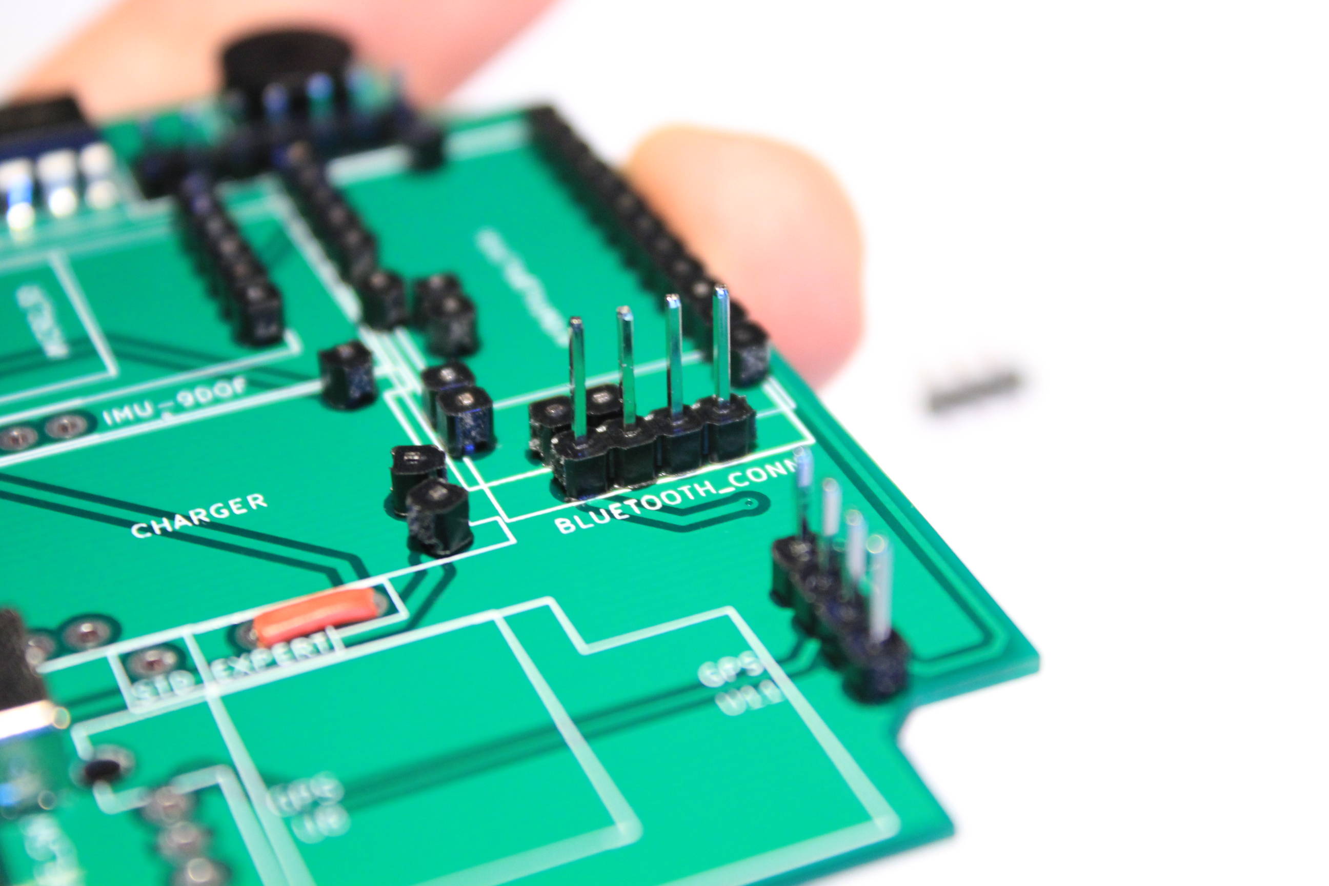
And four pins for the IMU connector.