Hardware
Building tutorial summary
Pin headers soldering
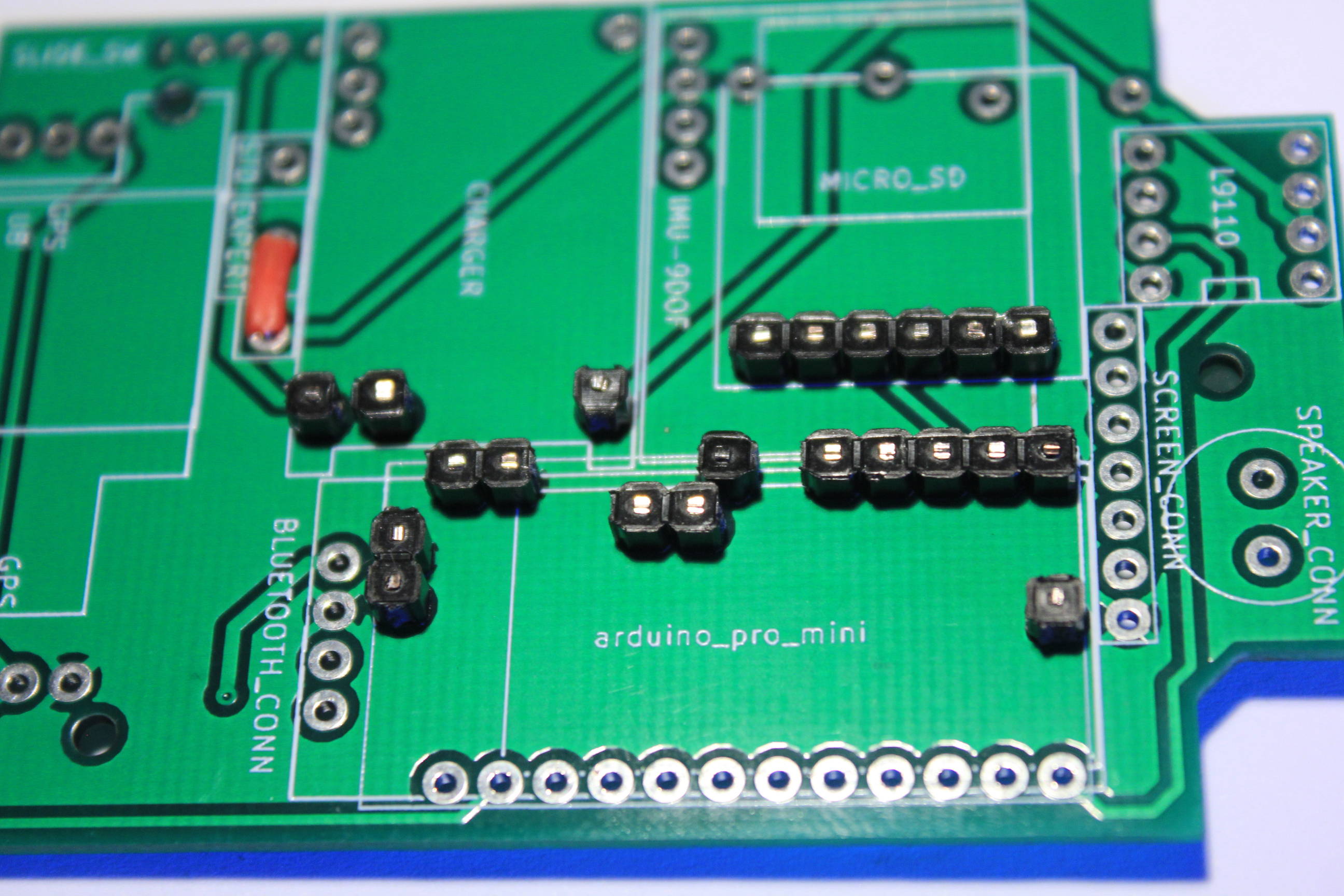
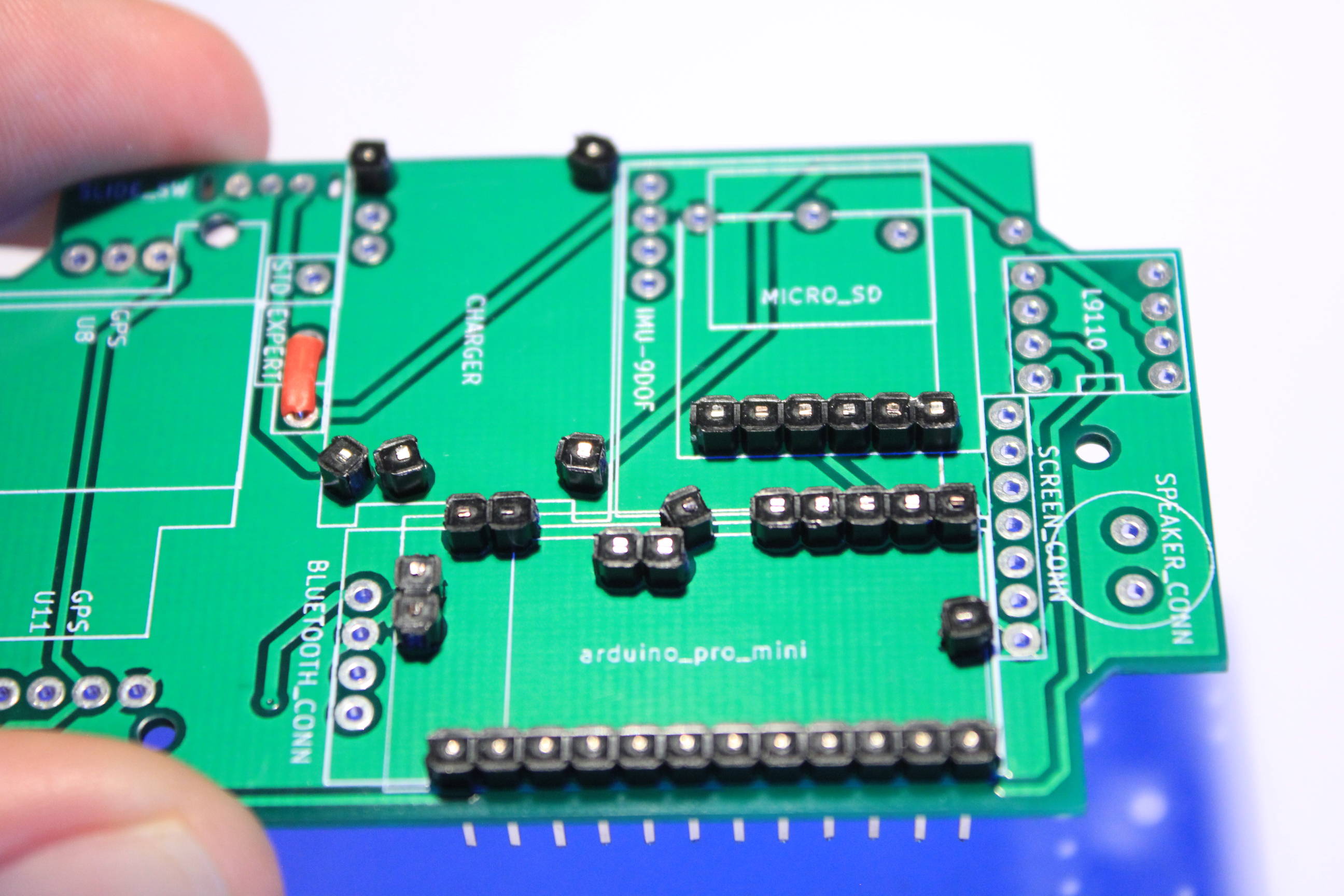
We need now to solder the pin headers to receive the component’s boards. Recall that the center pins must be soldered as flat as possible. Don’t hesitate to heat sufficiently to make the solder entering the pin’s holes. On the other hand, the pins along the PCB outline can be soldered with the amount of solder you want.
First take the pin headers that are headless and with the feet close to the PCB’s thickness.
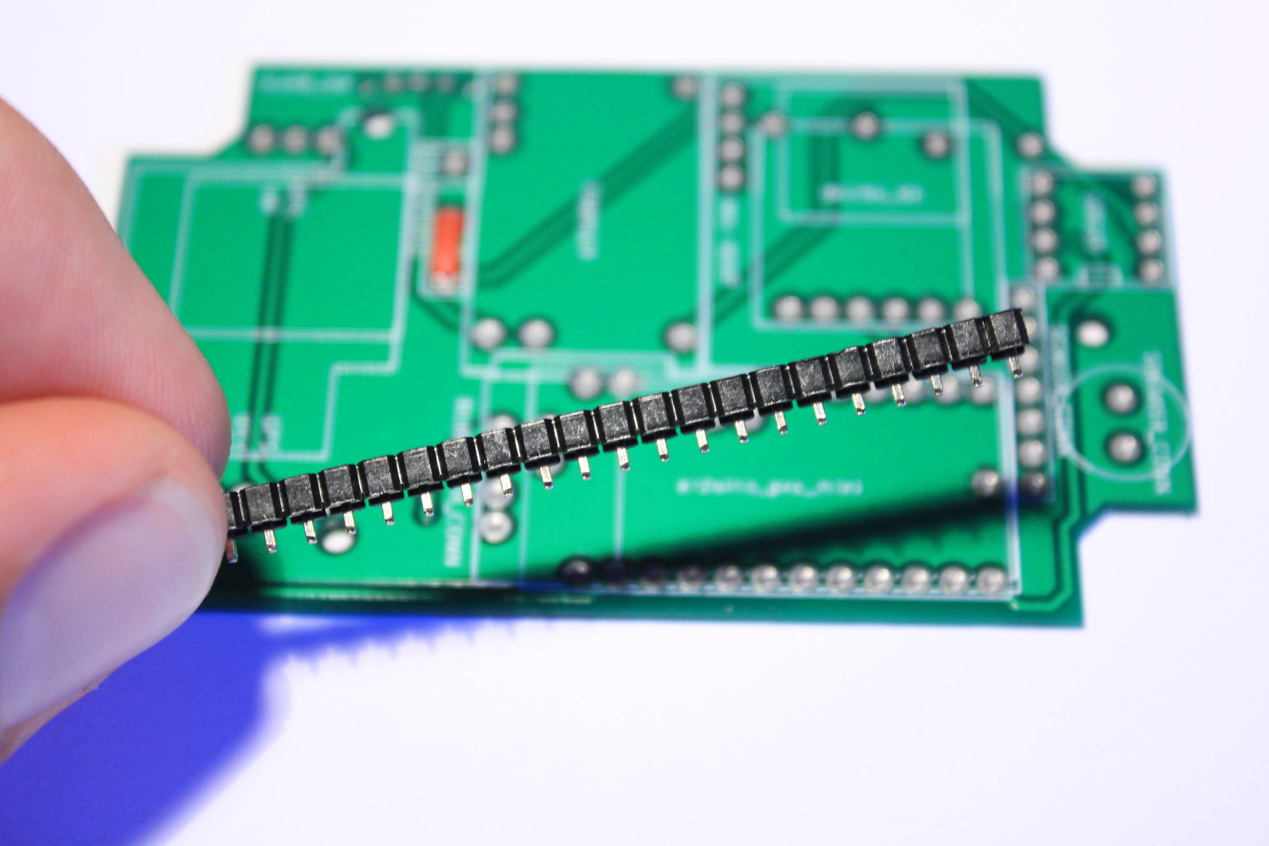
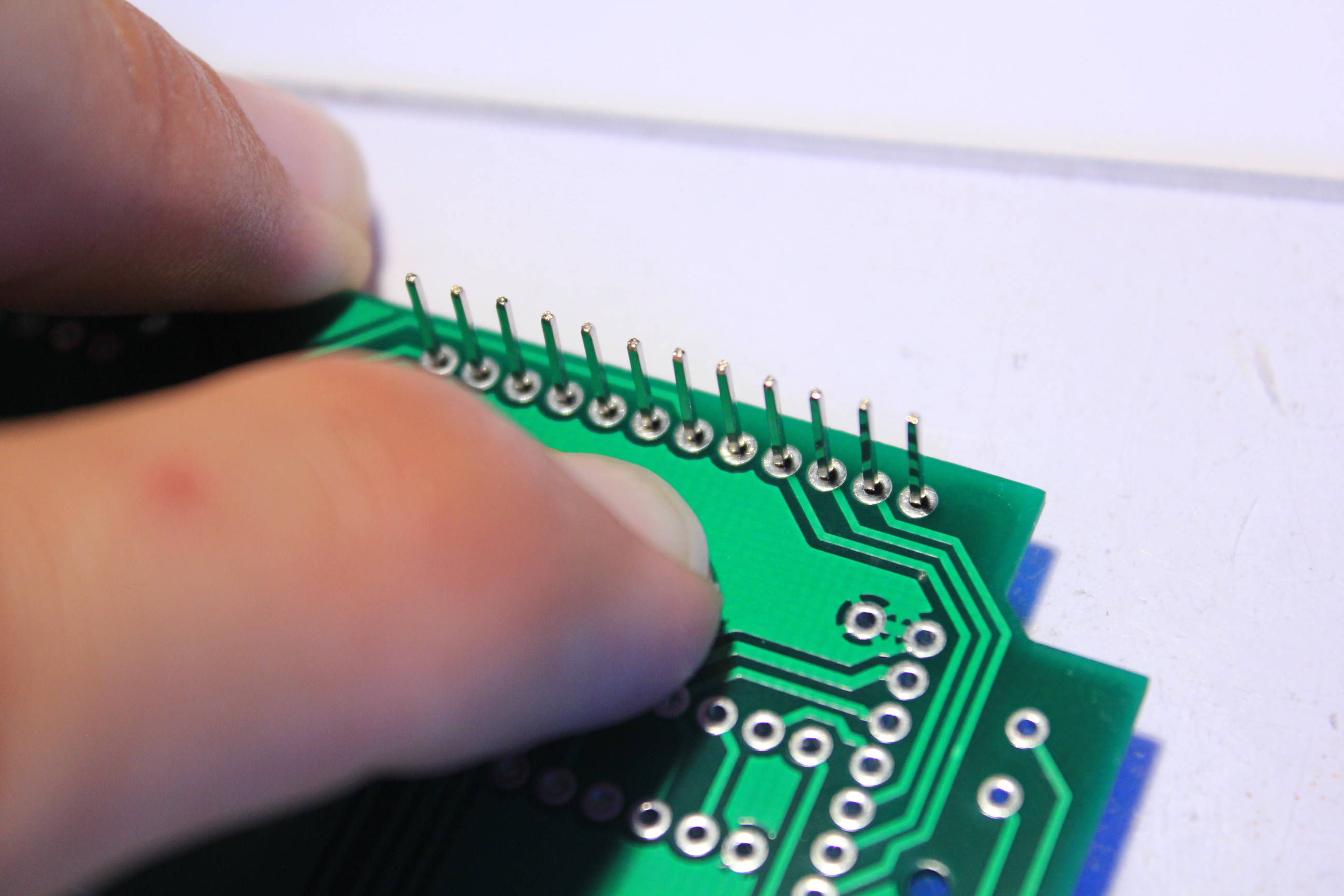
Prepare the pins for all the center holes like the image below. And keep these pins for the next step.
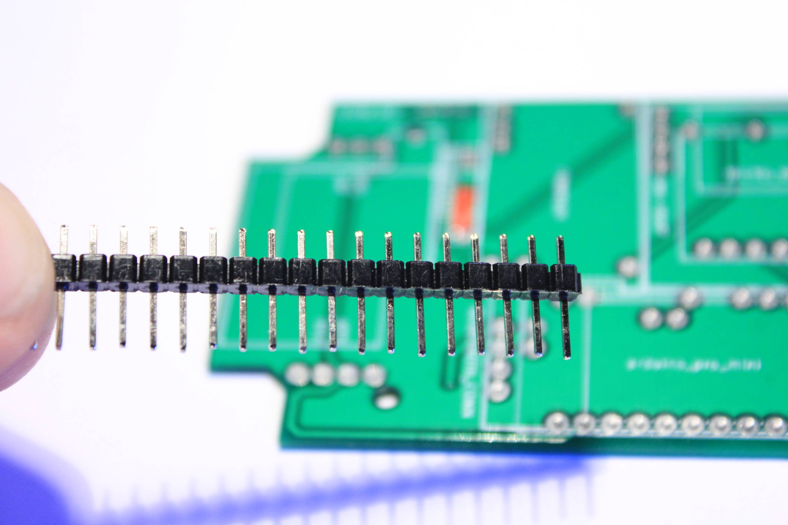
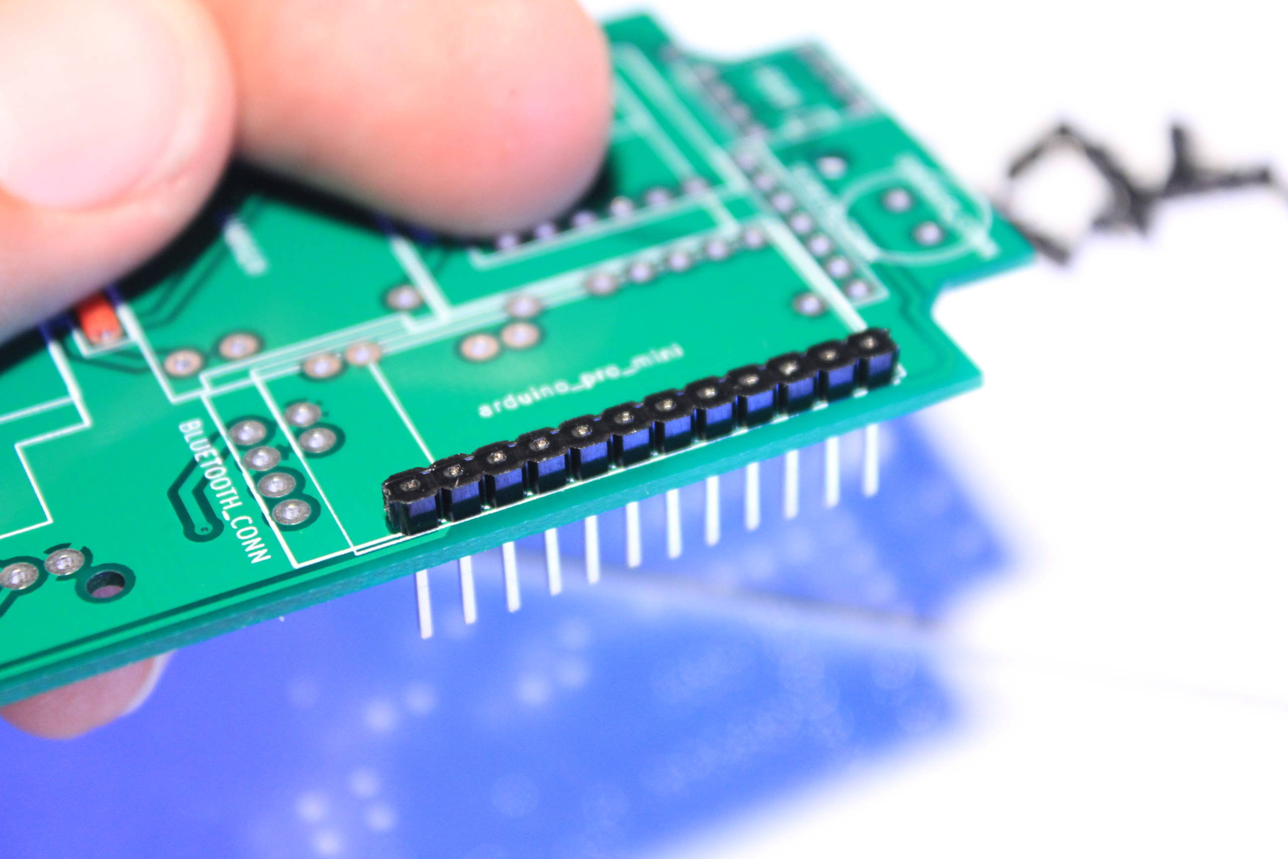
Next we can use the standard pin headers as we are close to the PCB outline and not over the battery. Flaten a row using the PCB like this :
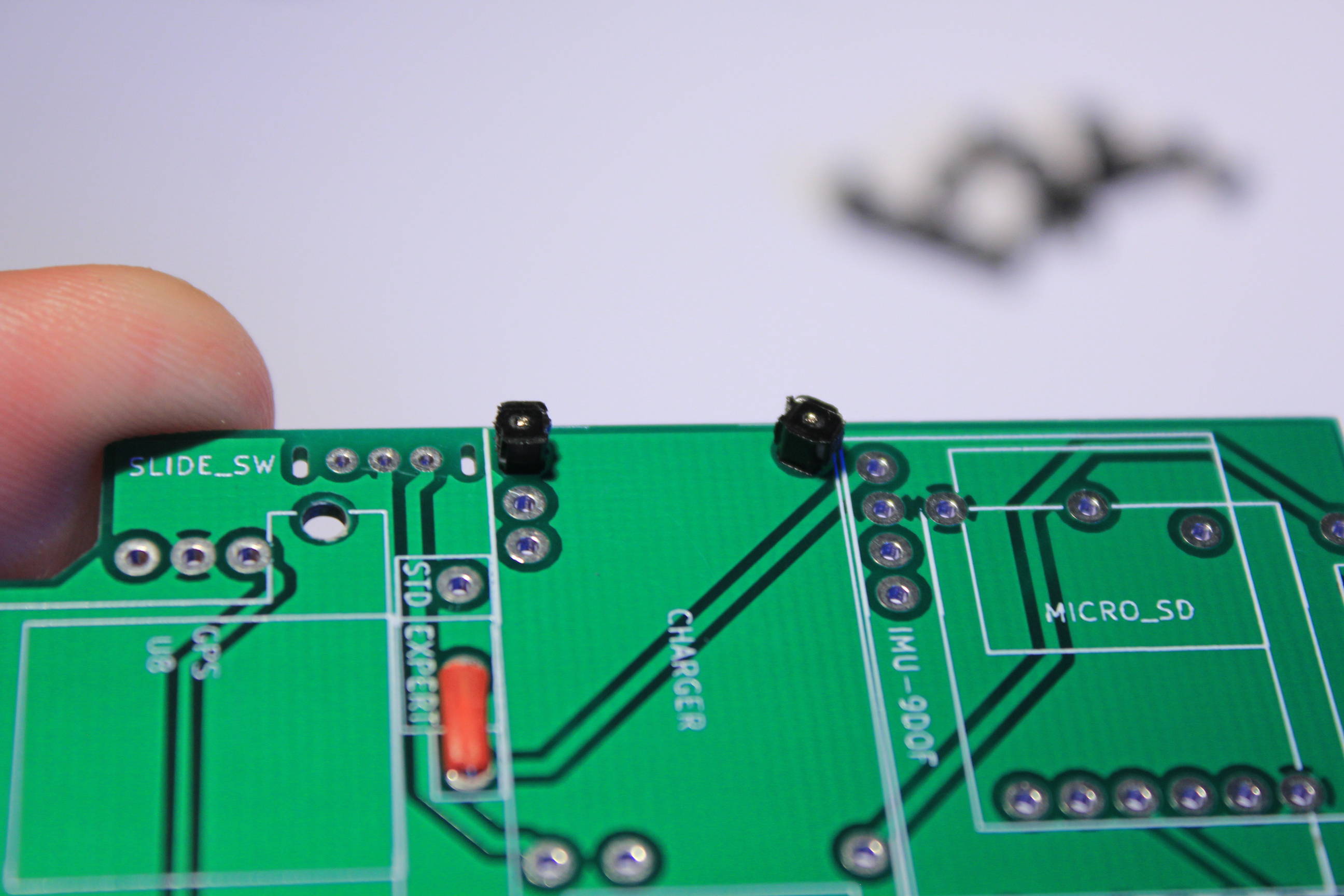
Repeat the same steps for the two outside pins of the charging board on the other side :
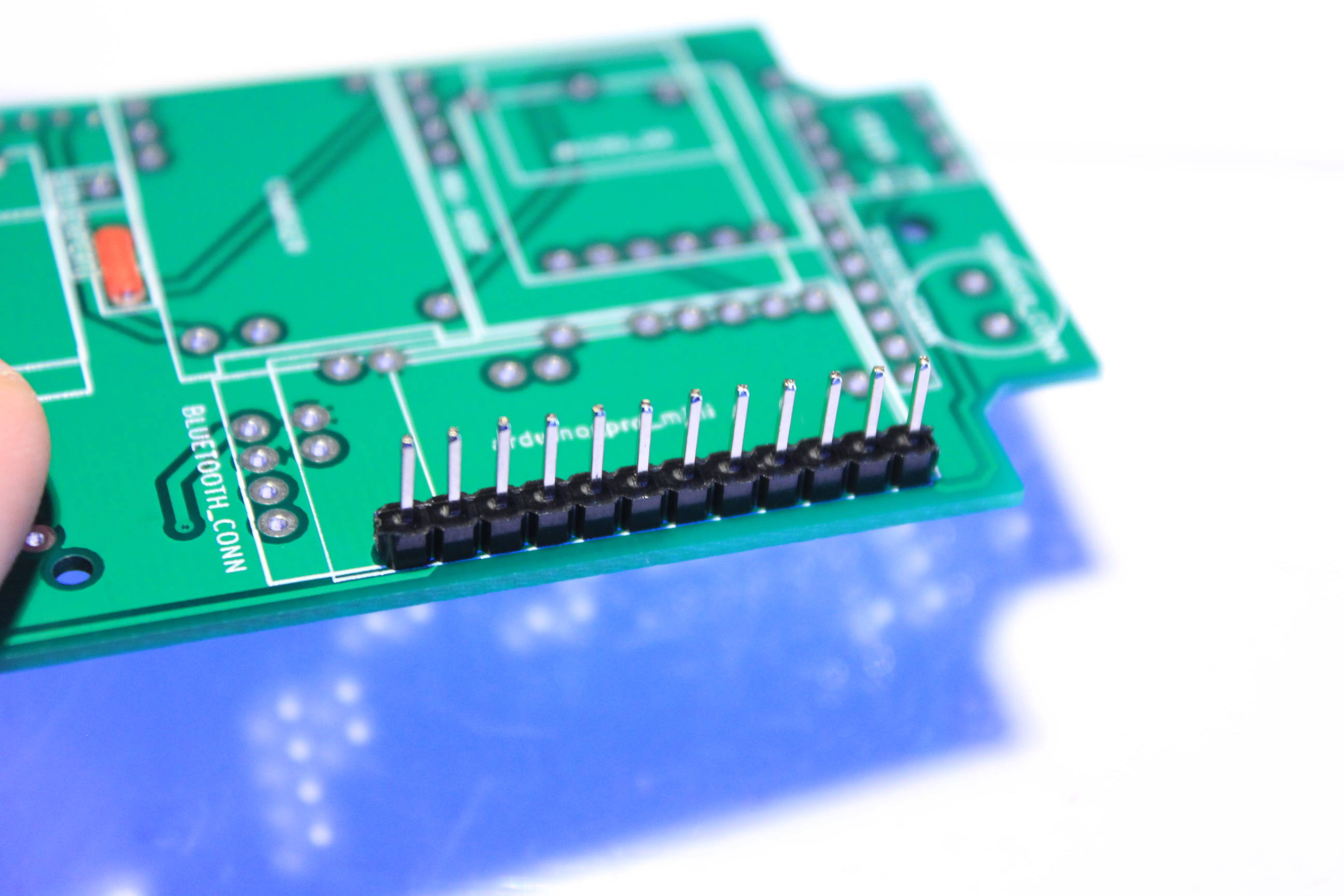
So we have now the standard pin headers :
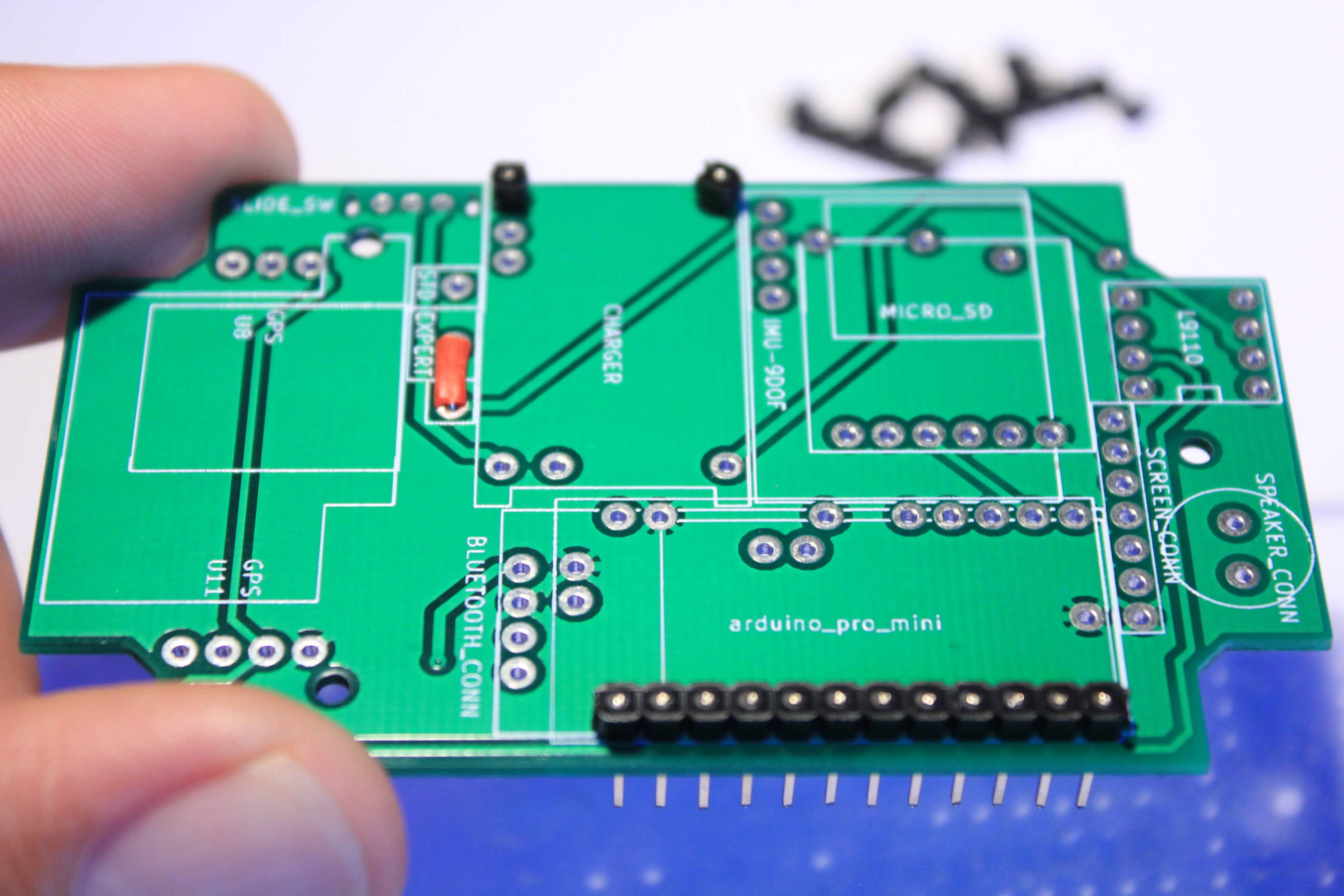
And all the small legs pin headers :
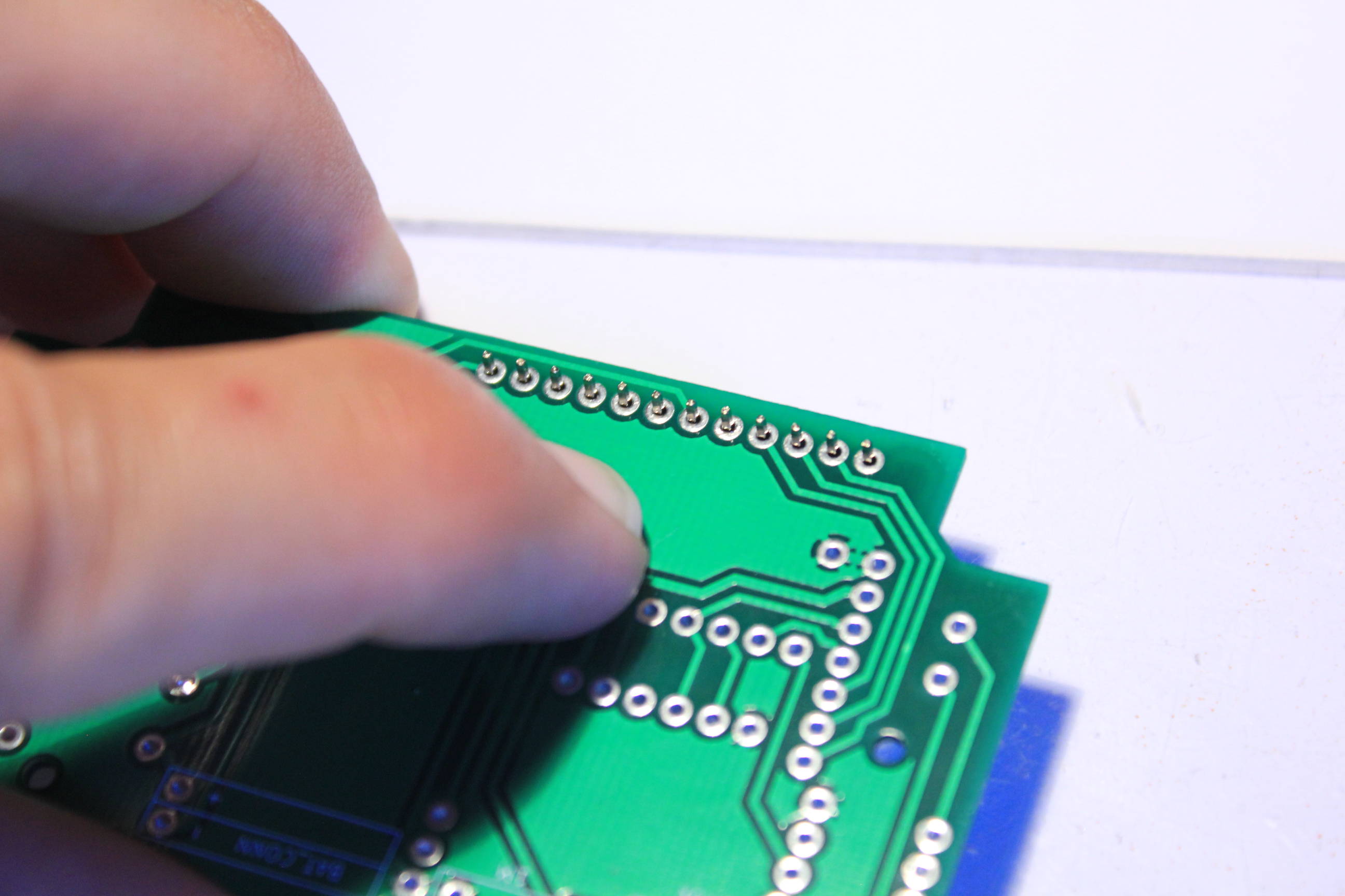
Use now something to return the PCB on the table :
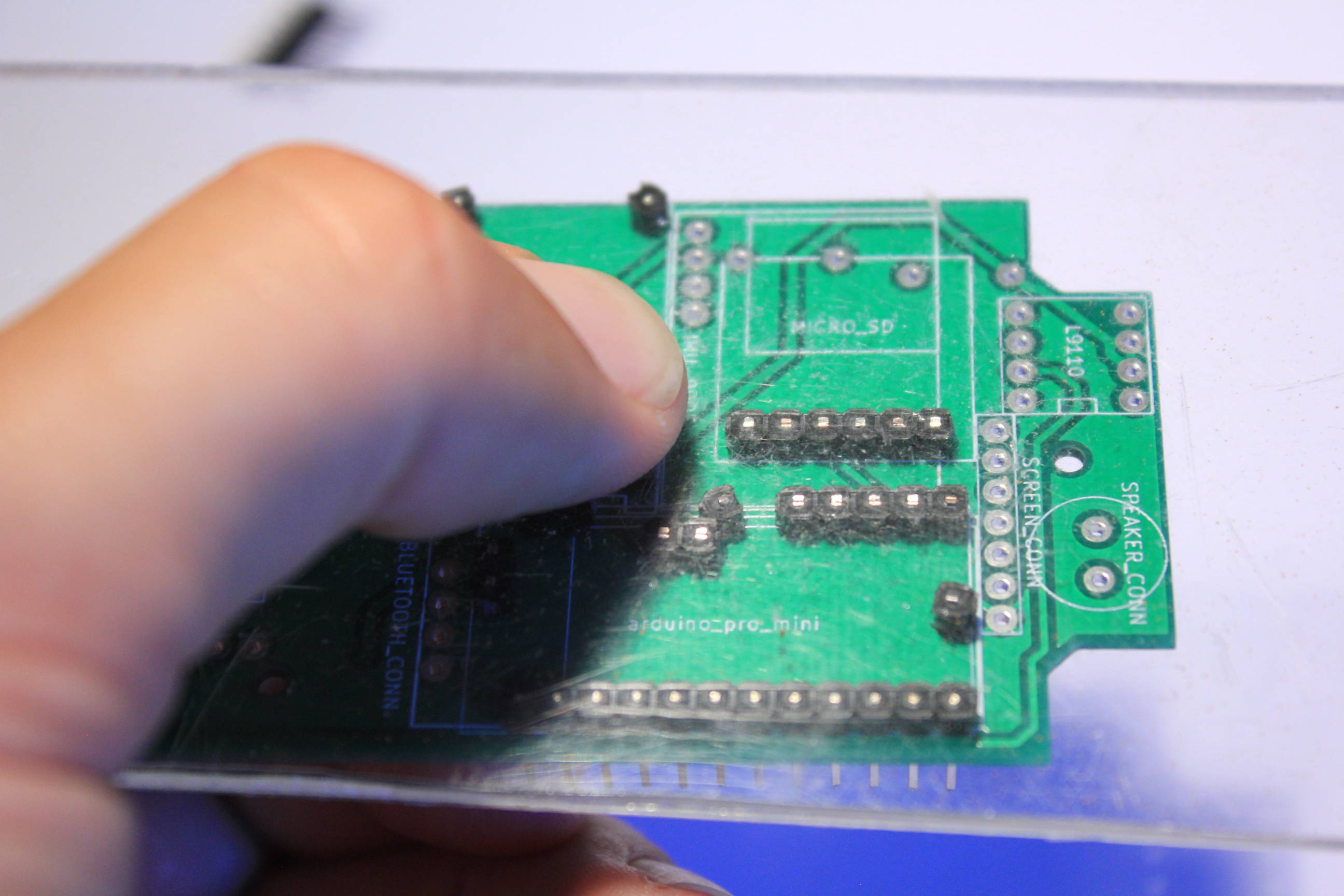
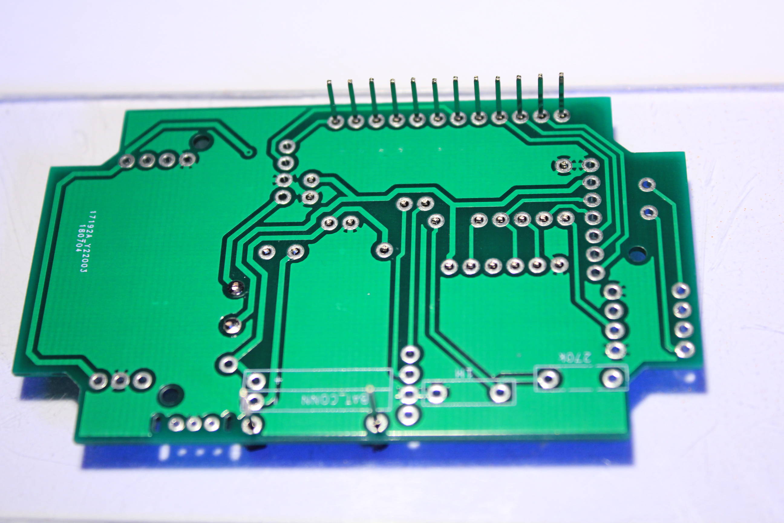
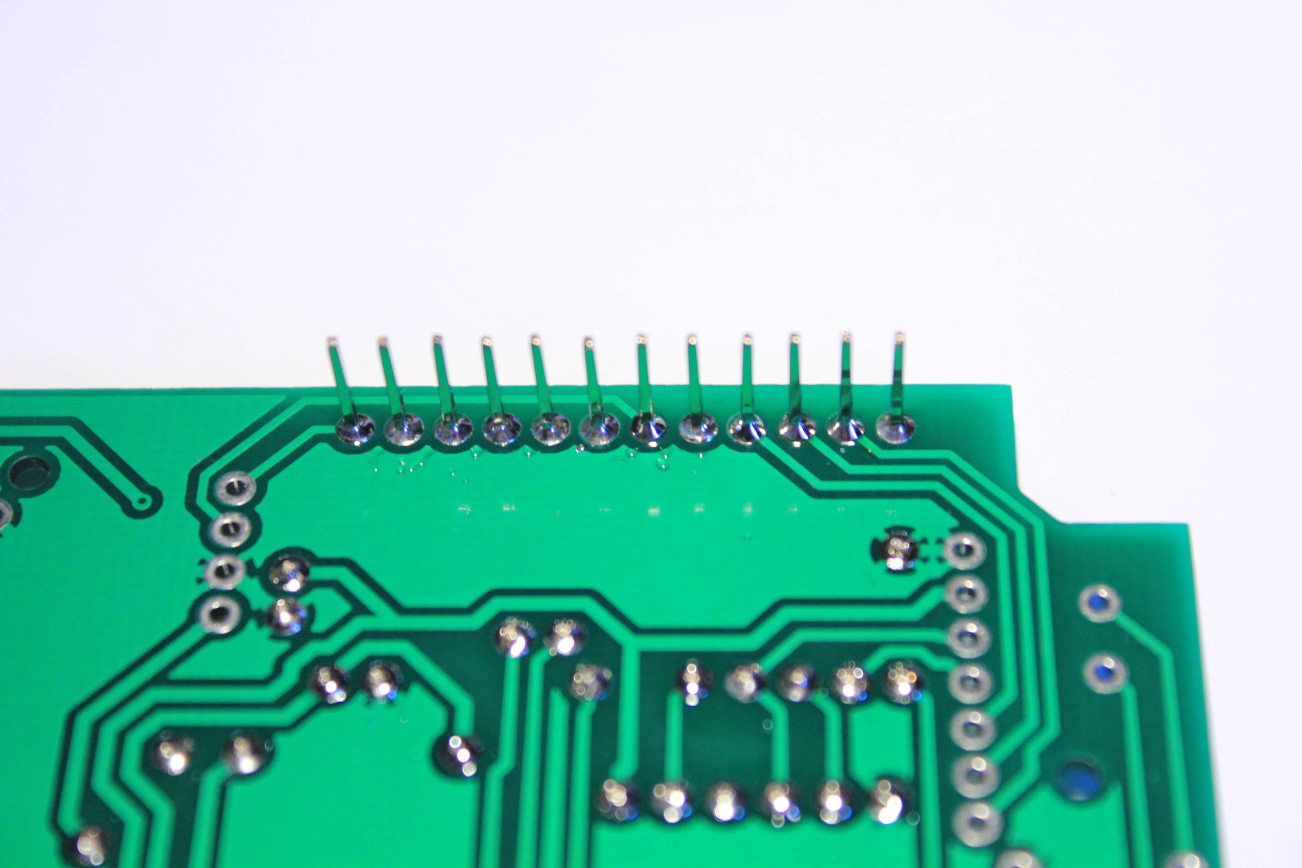
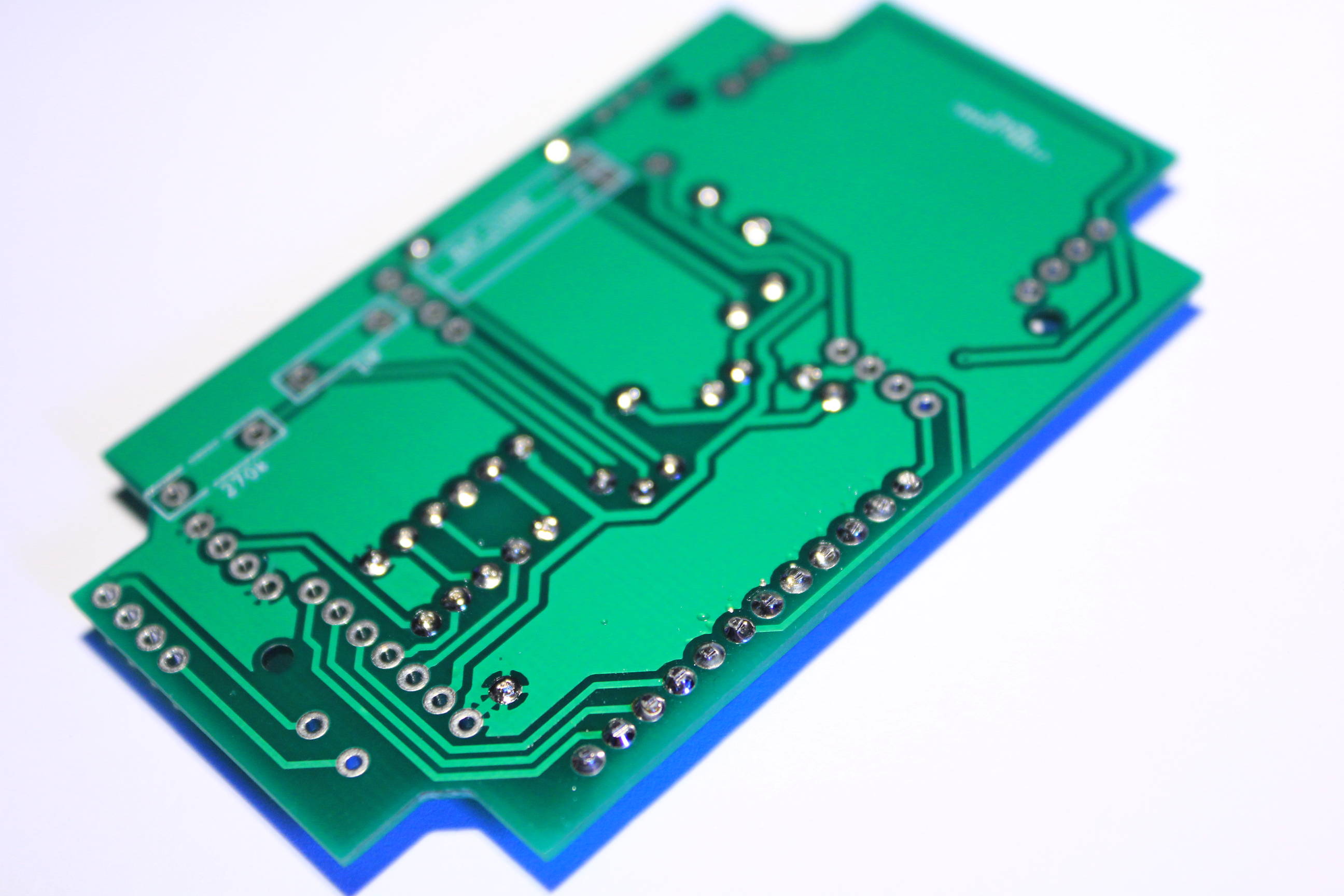
Solder the center pins as flat as possible. I usually apply the amount needed to see only the top of the pin.
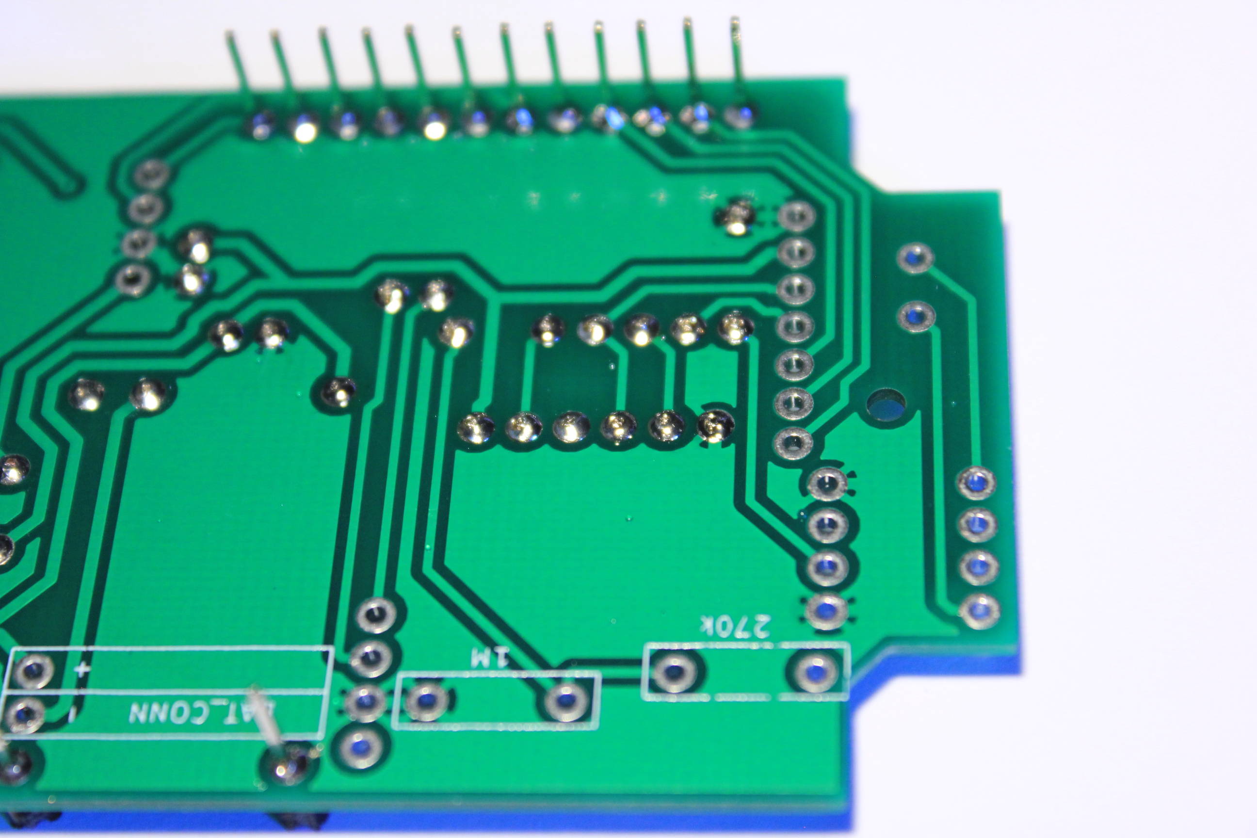
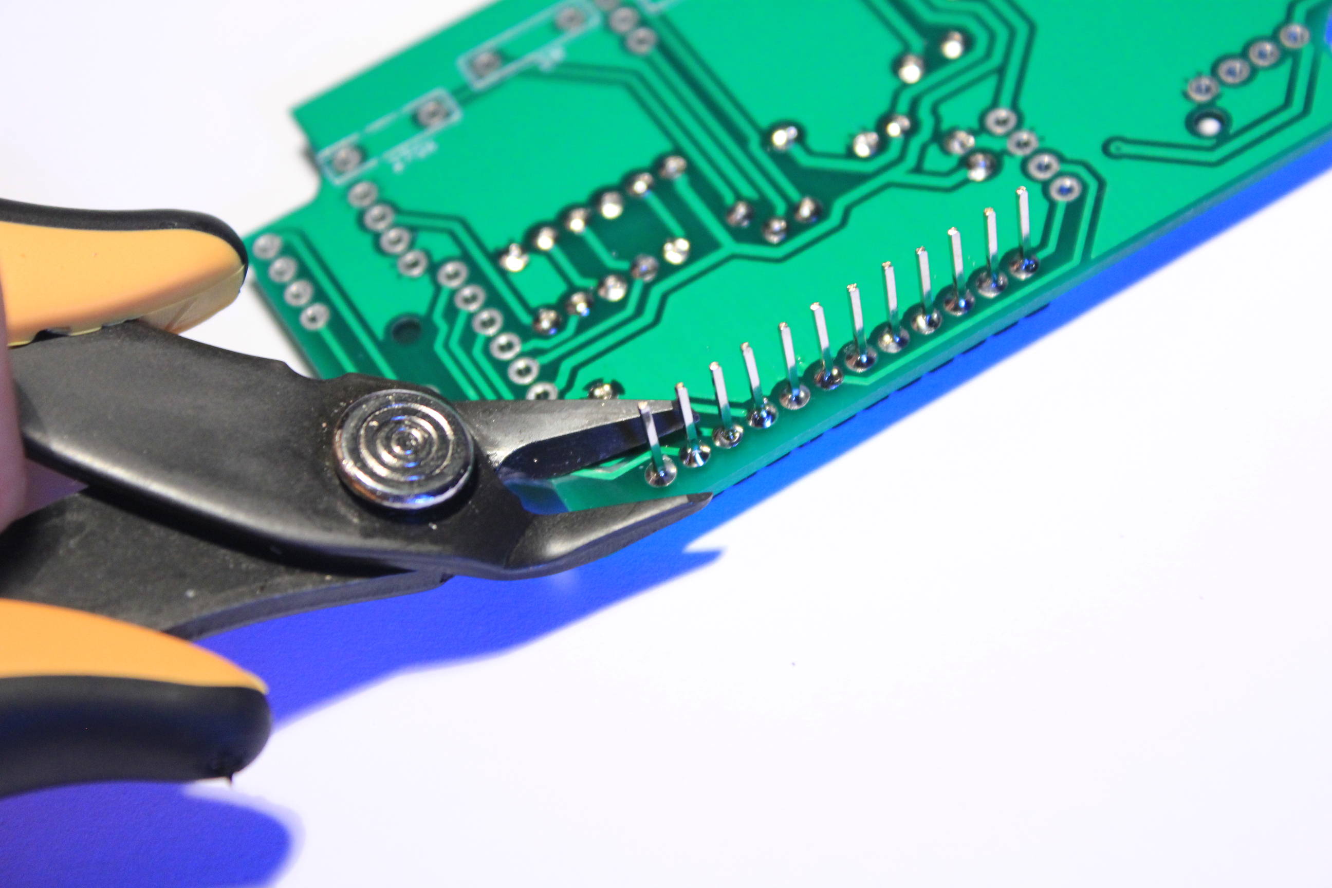
Solder the outer pins and cut the pin’s end.