Hardware
Building tutorial summary
Soldering backside components
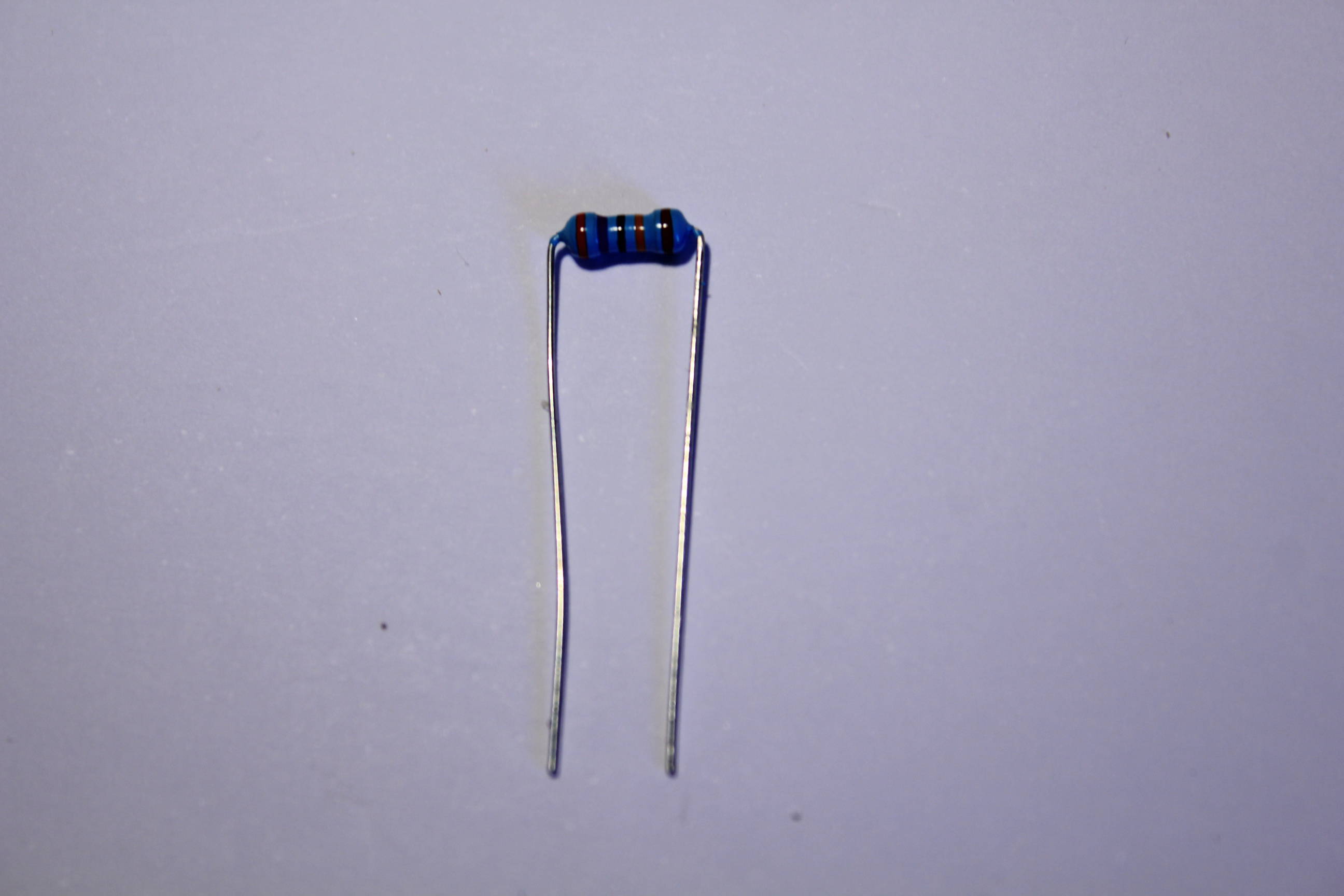
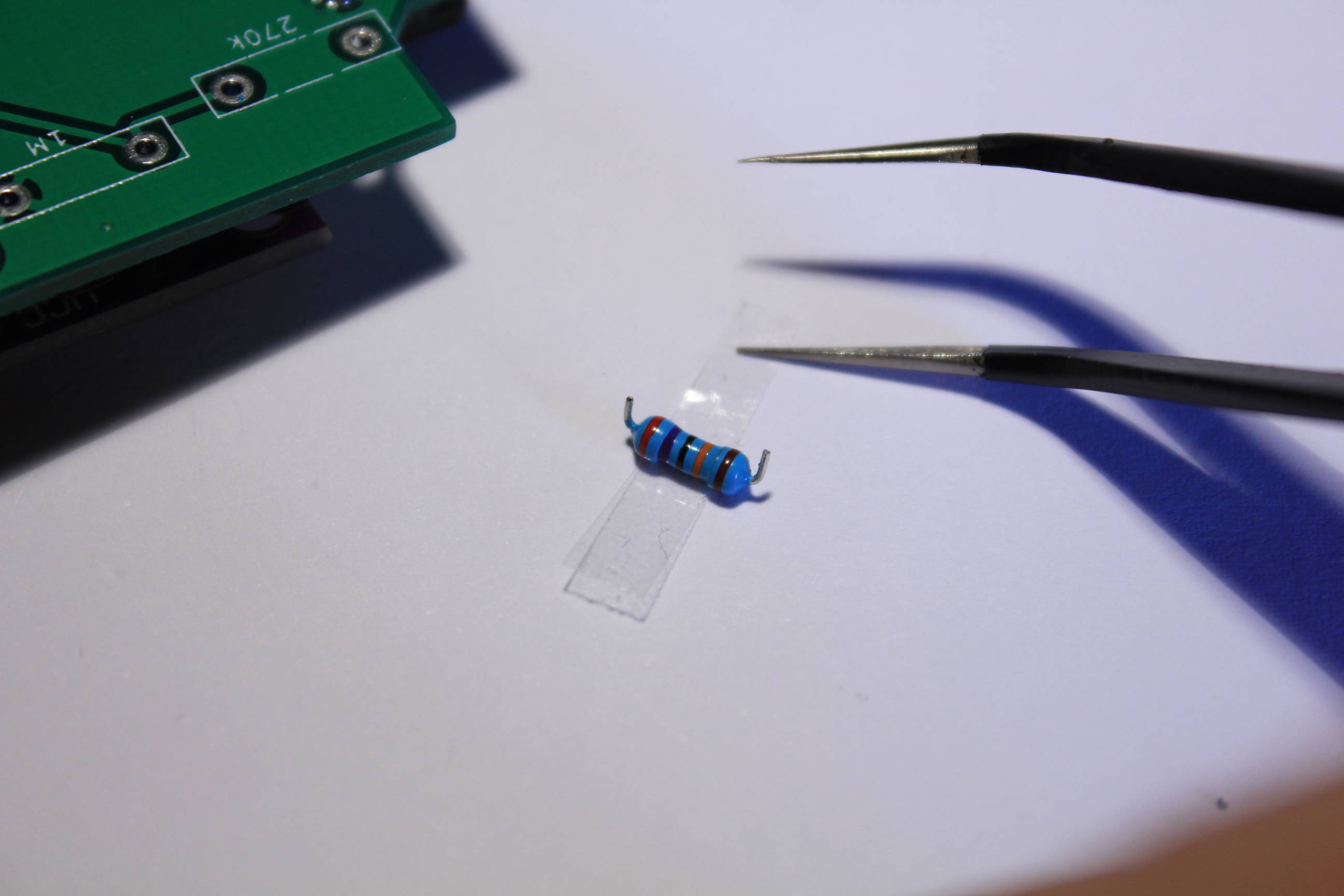
Take the 1M and the 270k resistors and bend the tips as close as possible of the resistor’s body.
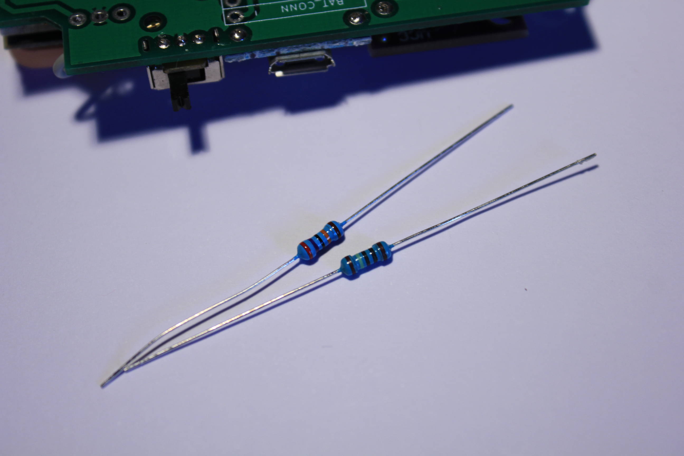
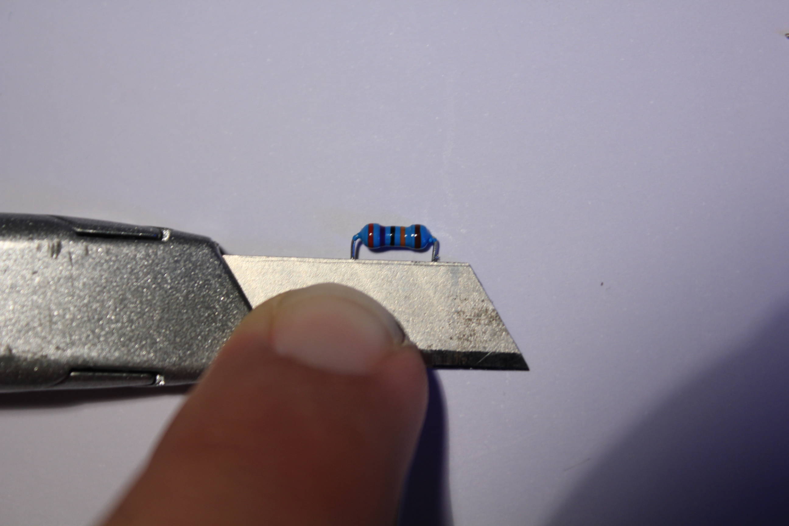
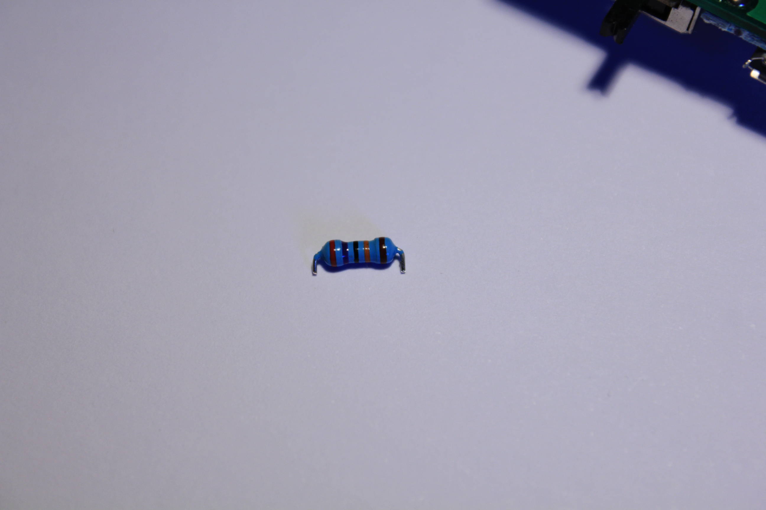
You need to cut the pins just under the resistor’s bottom. The pins need to be long enough to enter the PCB holes but not too much to not pass through the PCB.
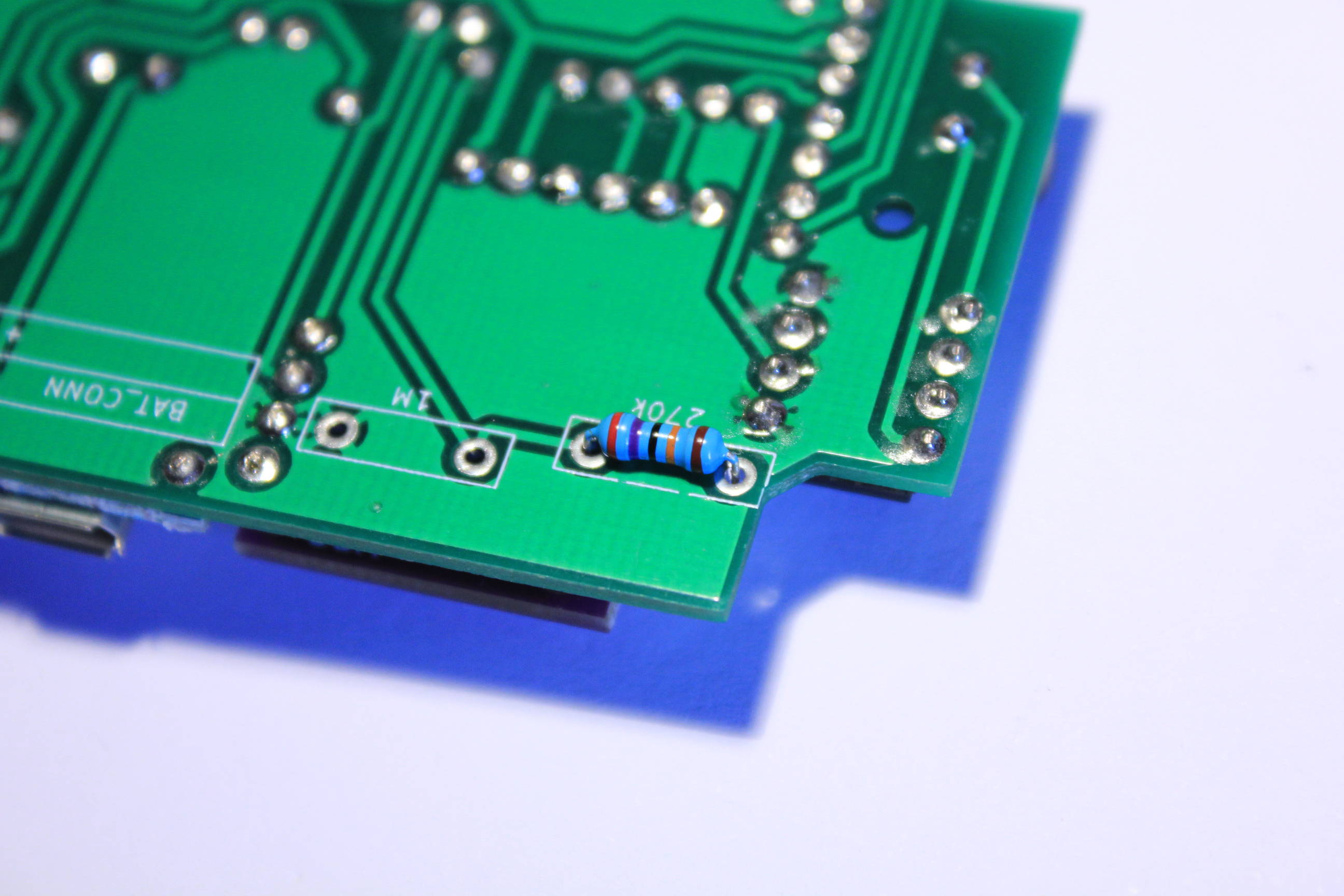
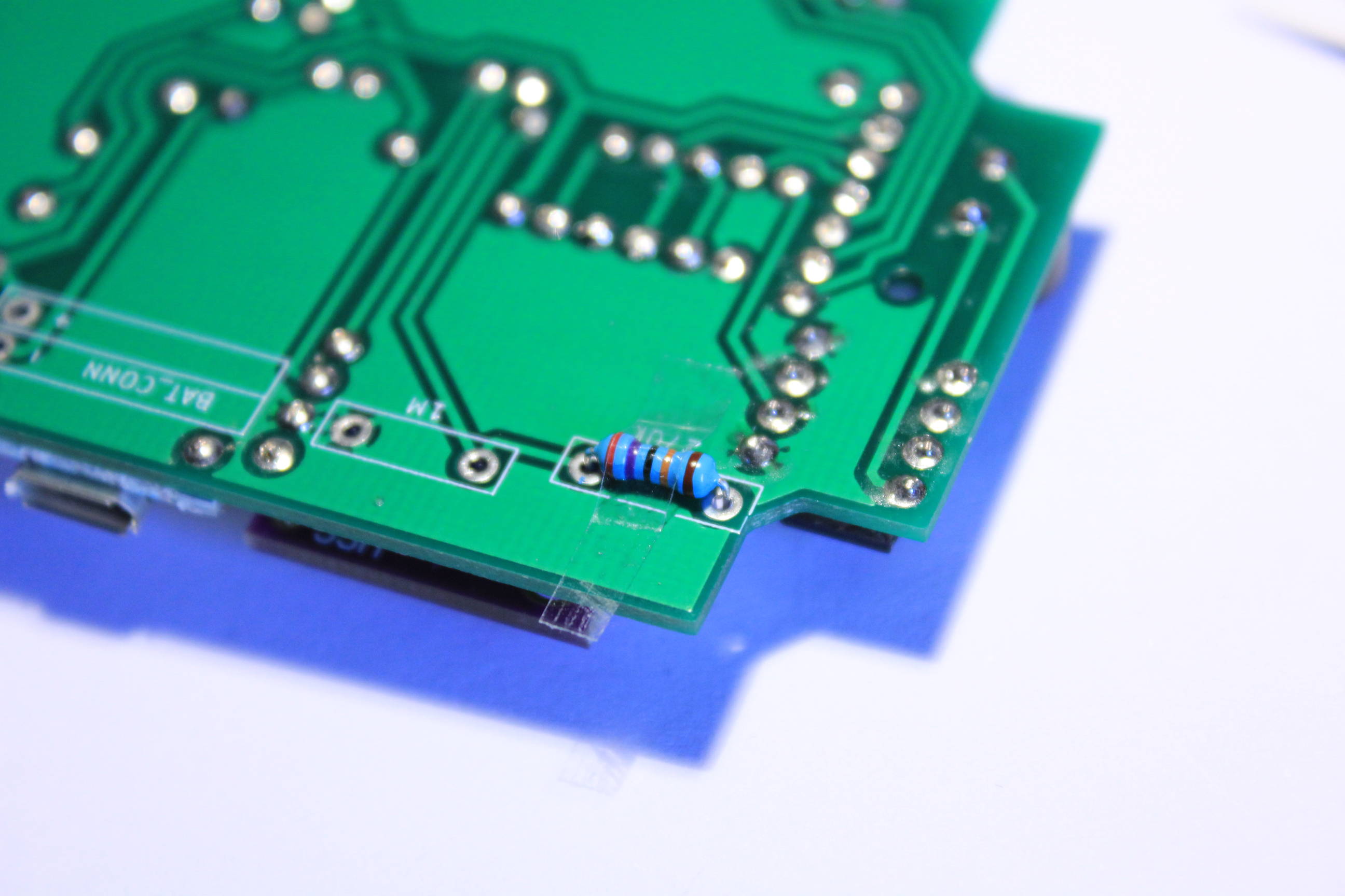
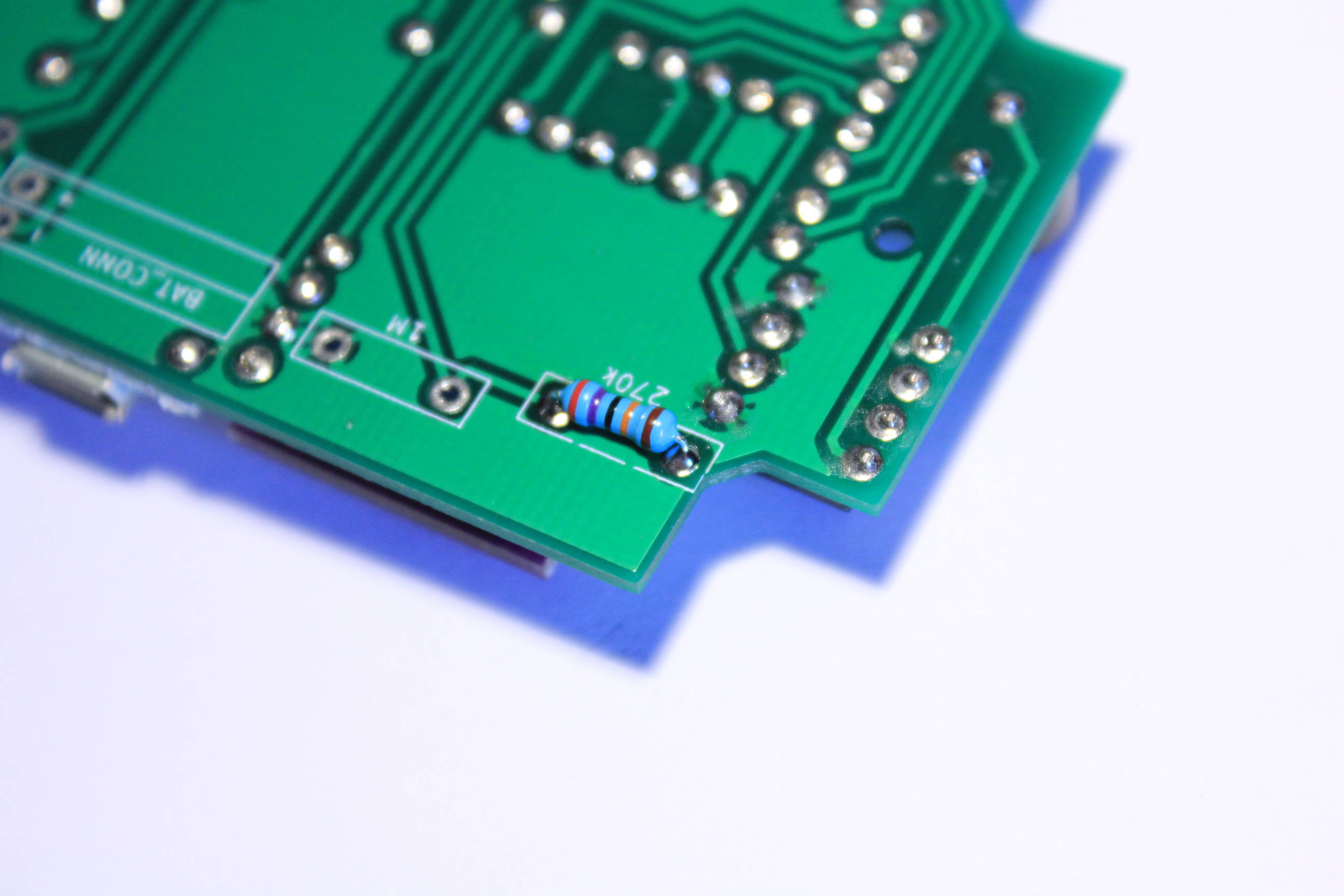
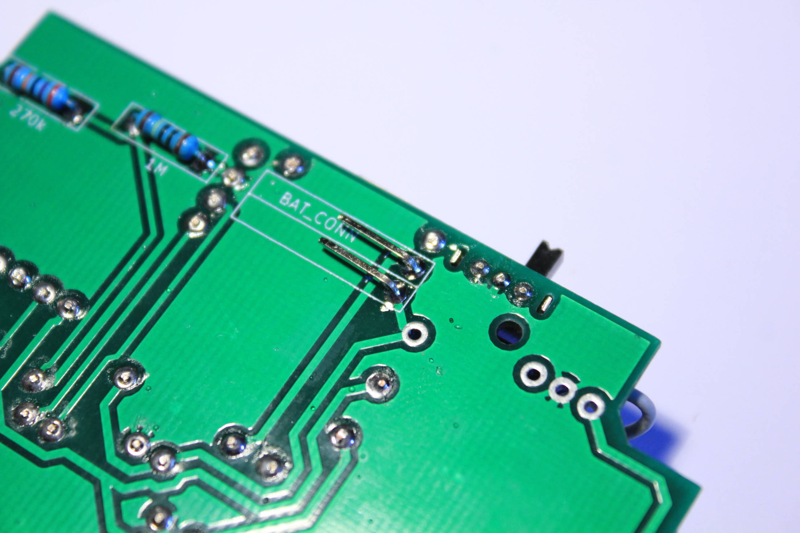
Put the 270k resistor on tape, place it on the PCB and solder it.
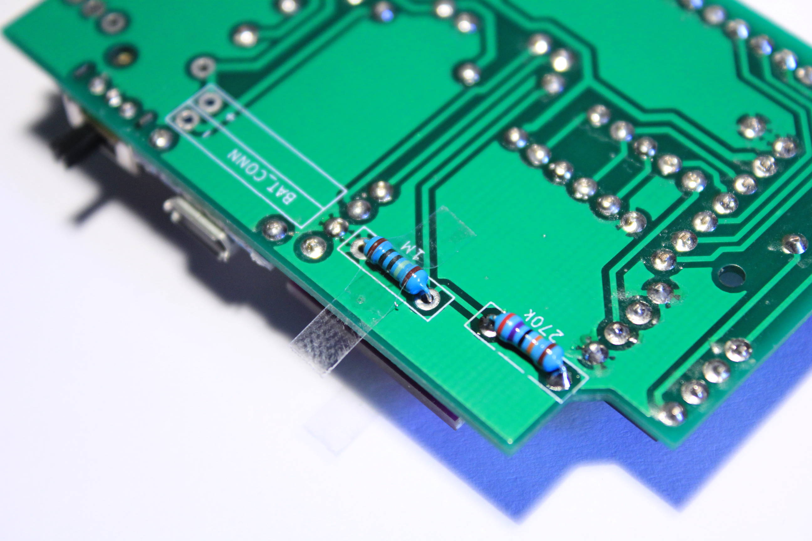
Same thing for the 1M resistor.
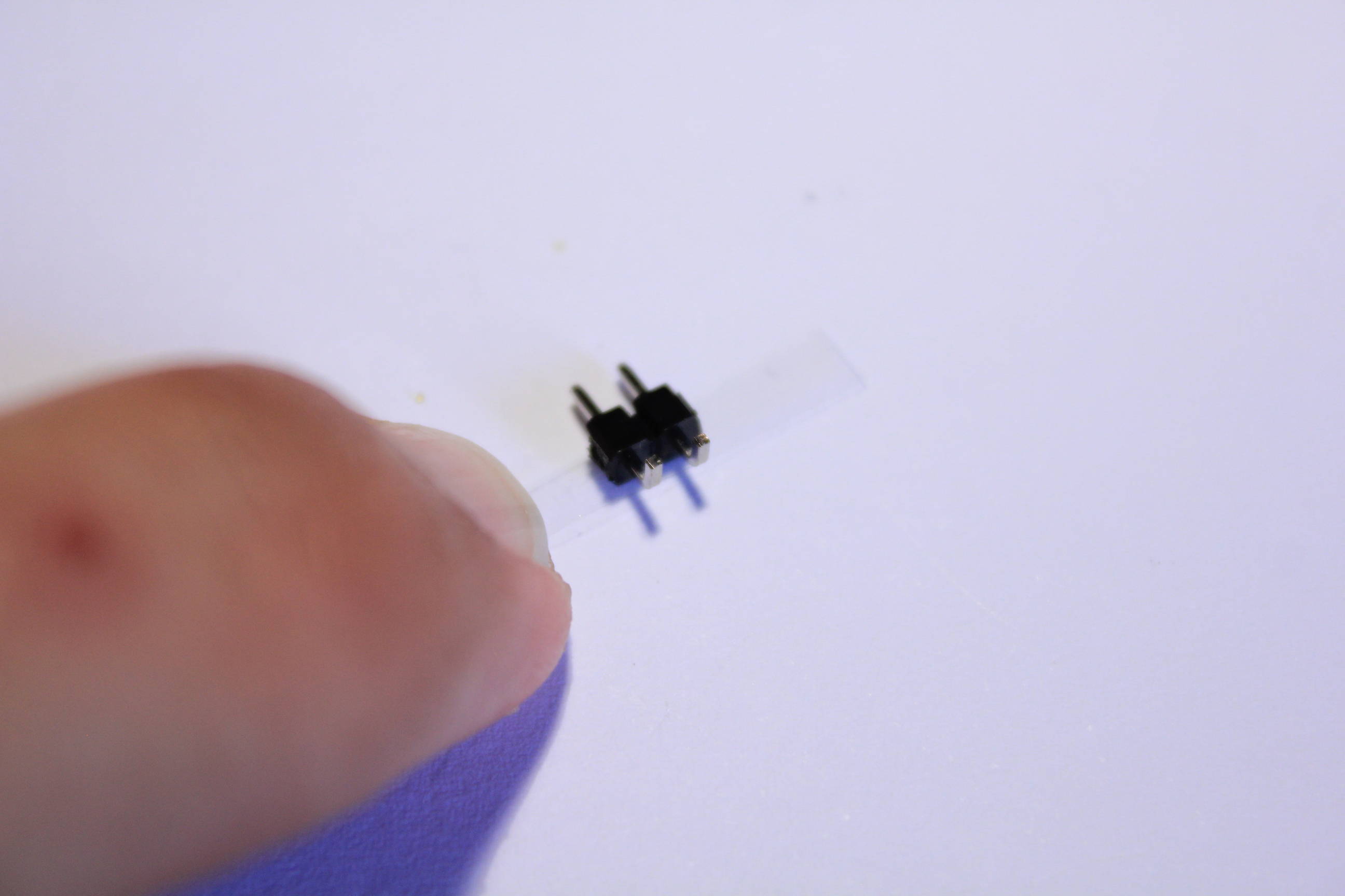
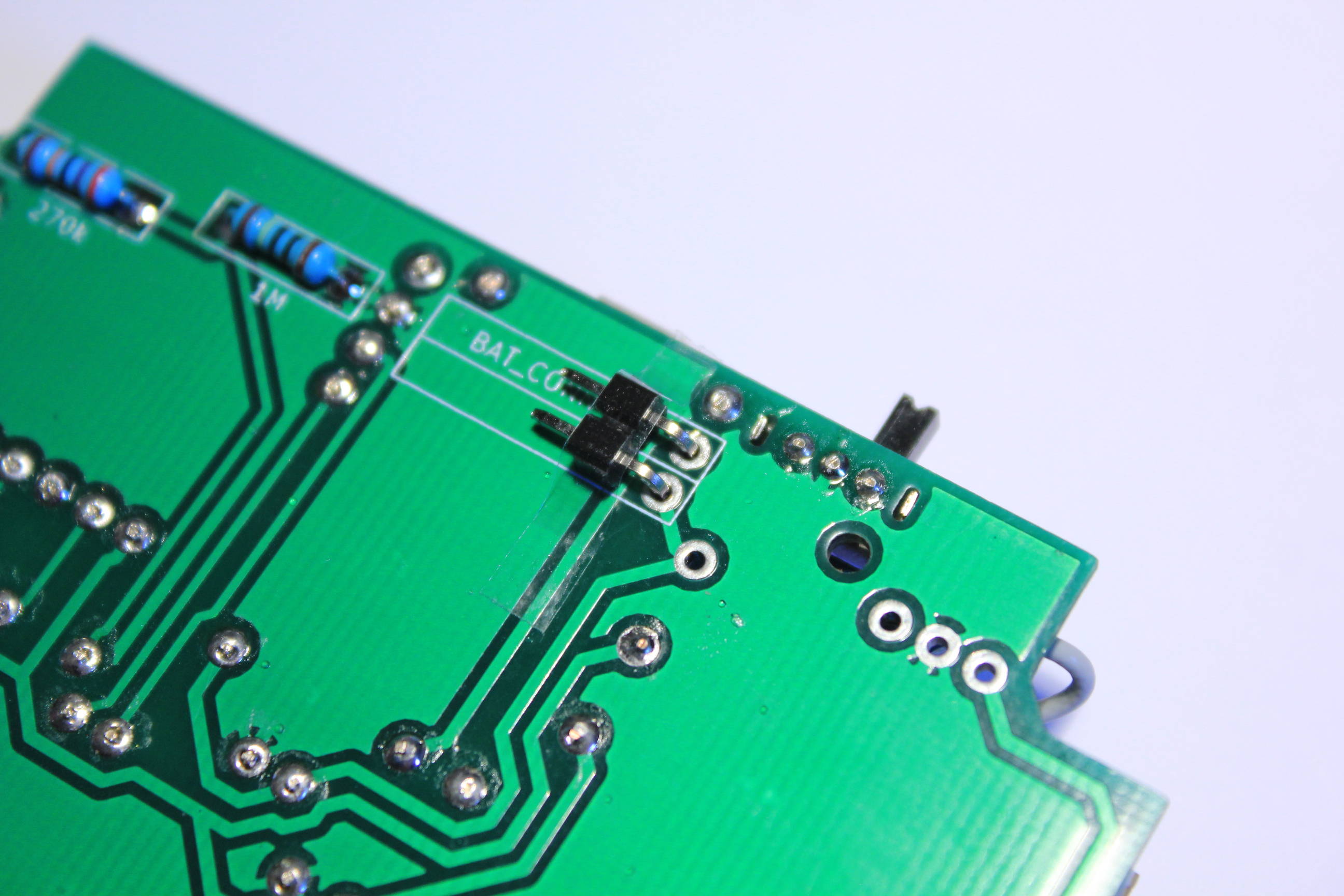
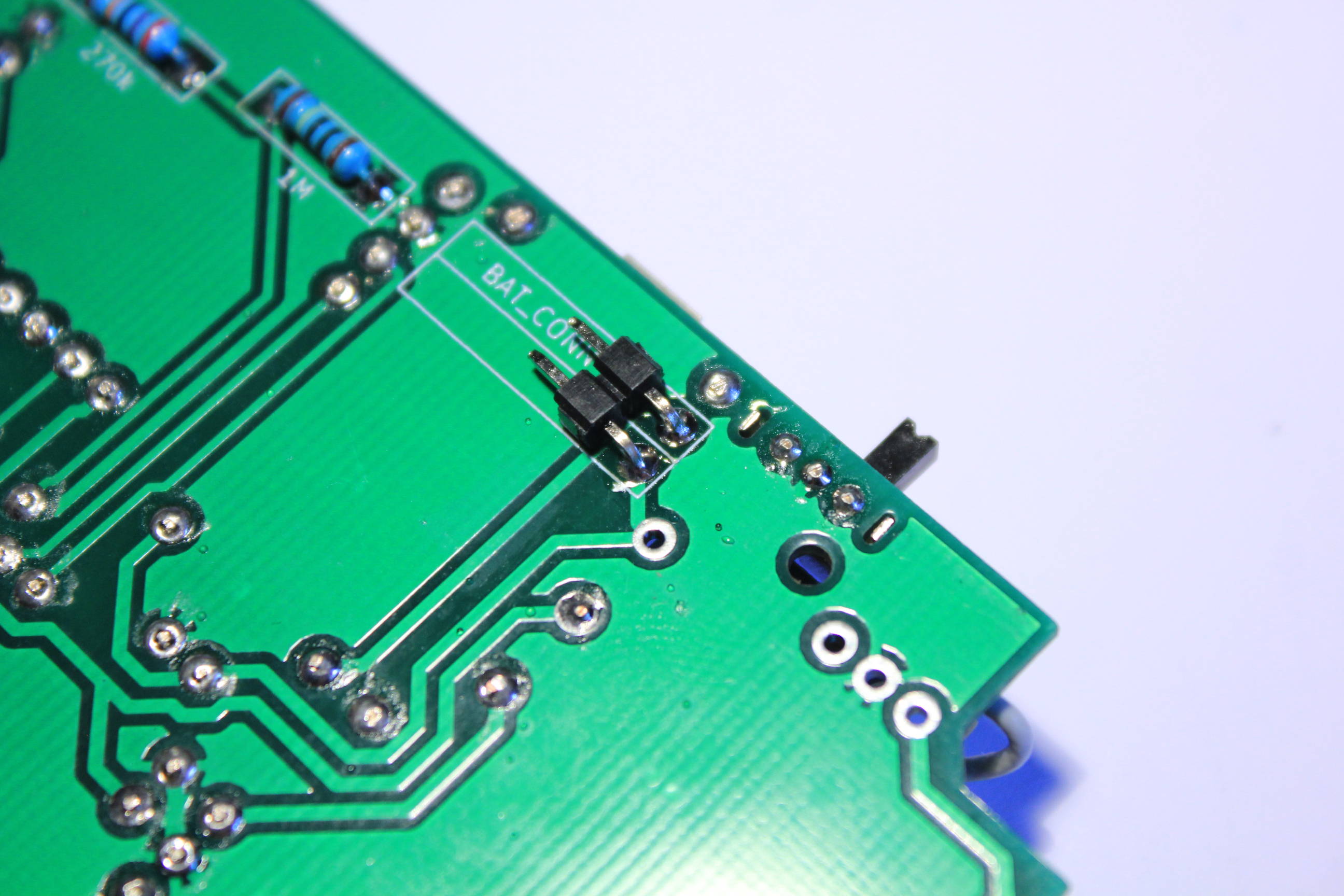
With the same method solder the battery connector and remove the insulation.
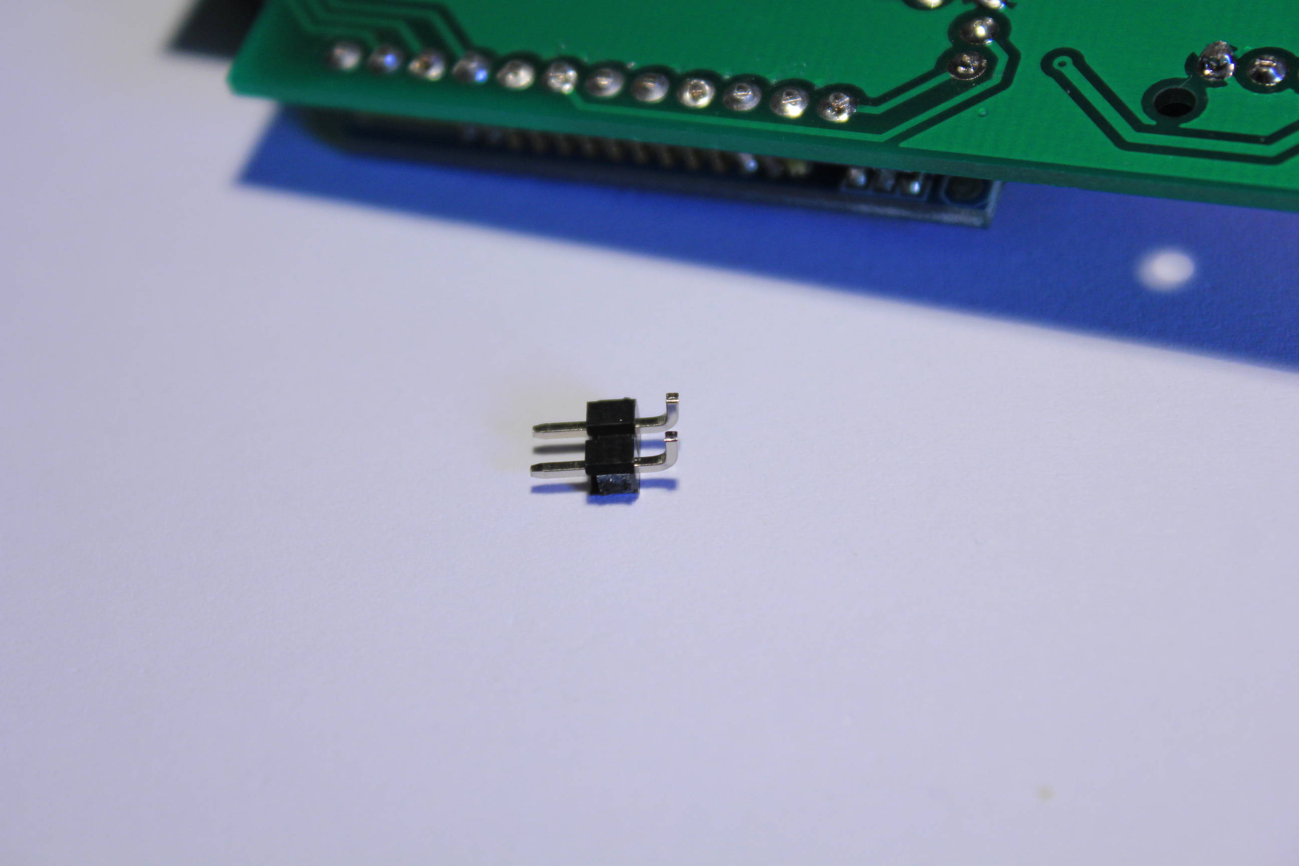
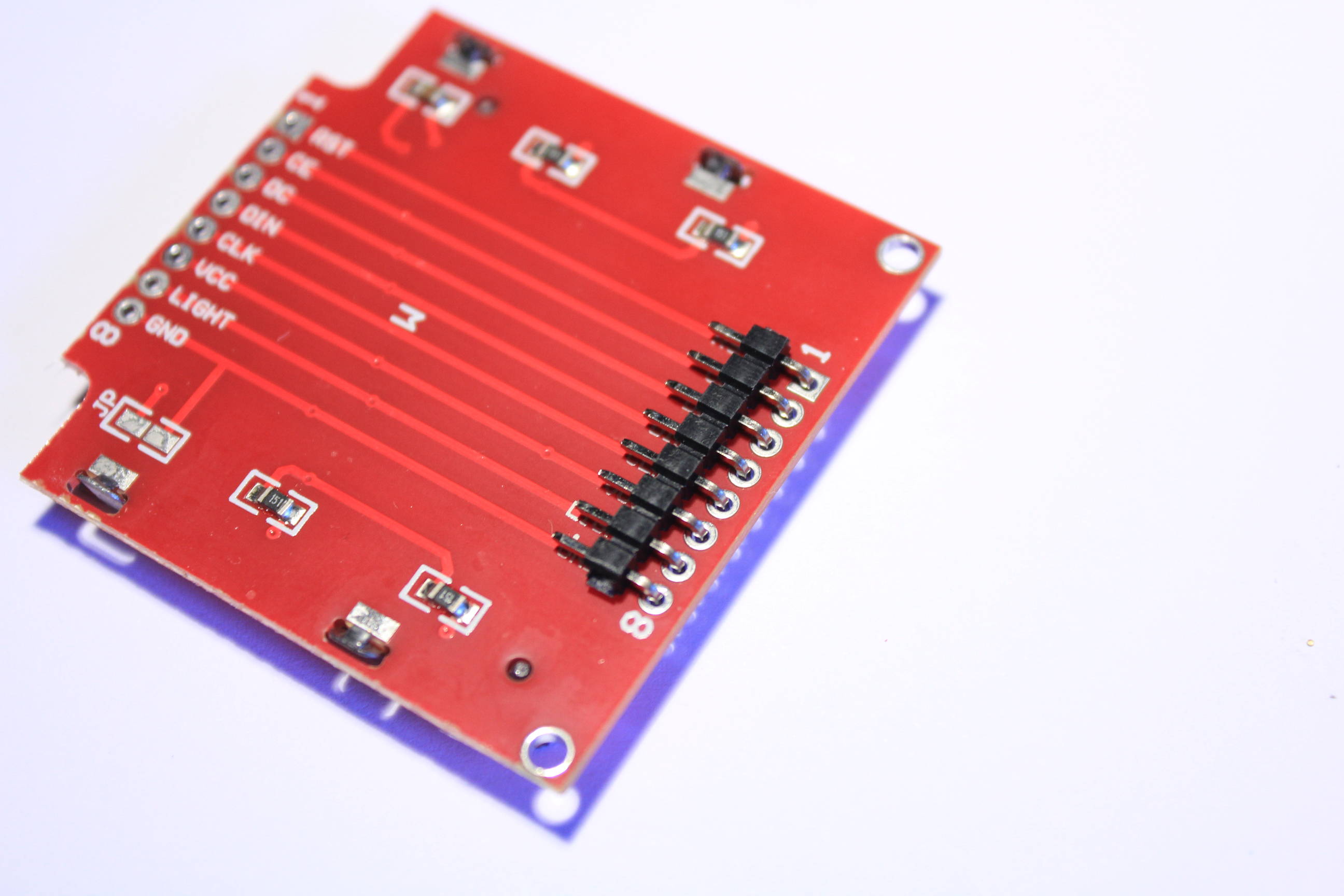
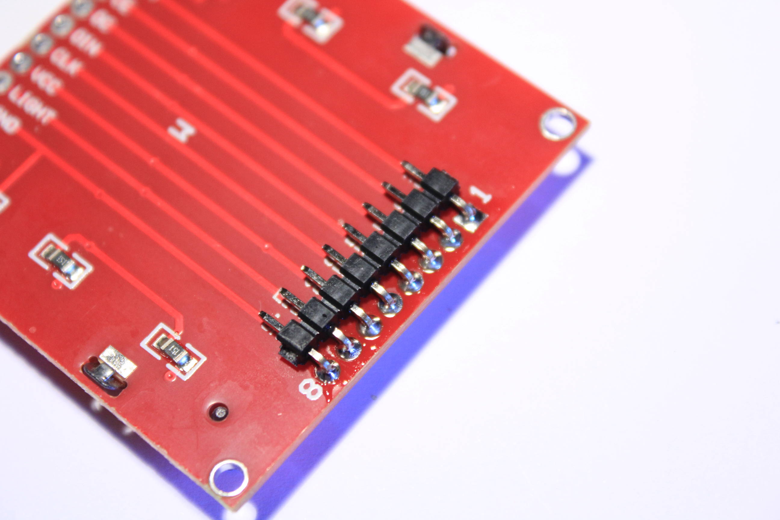
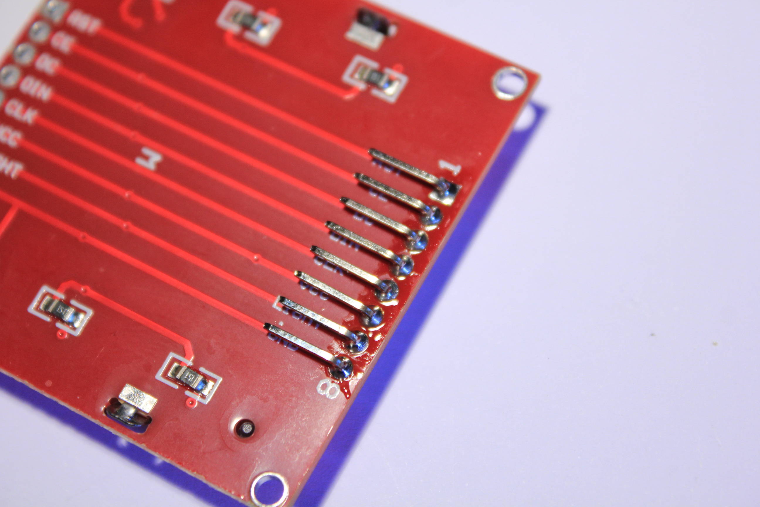
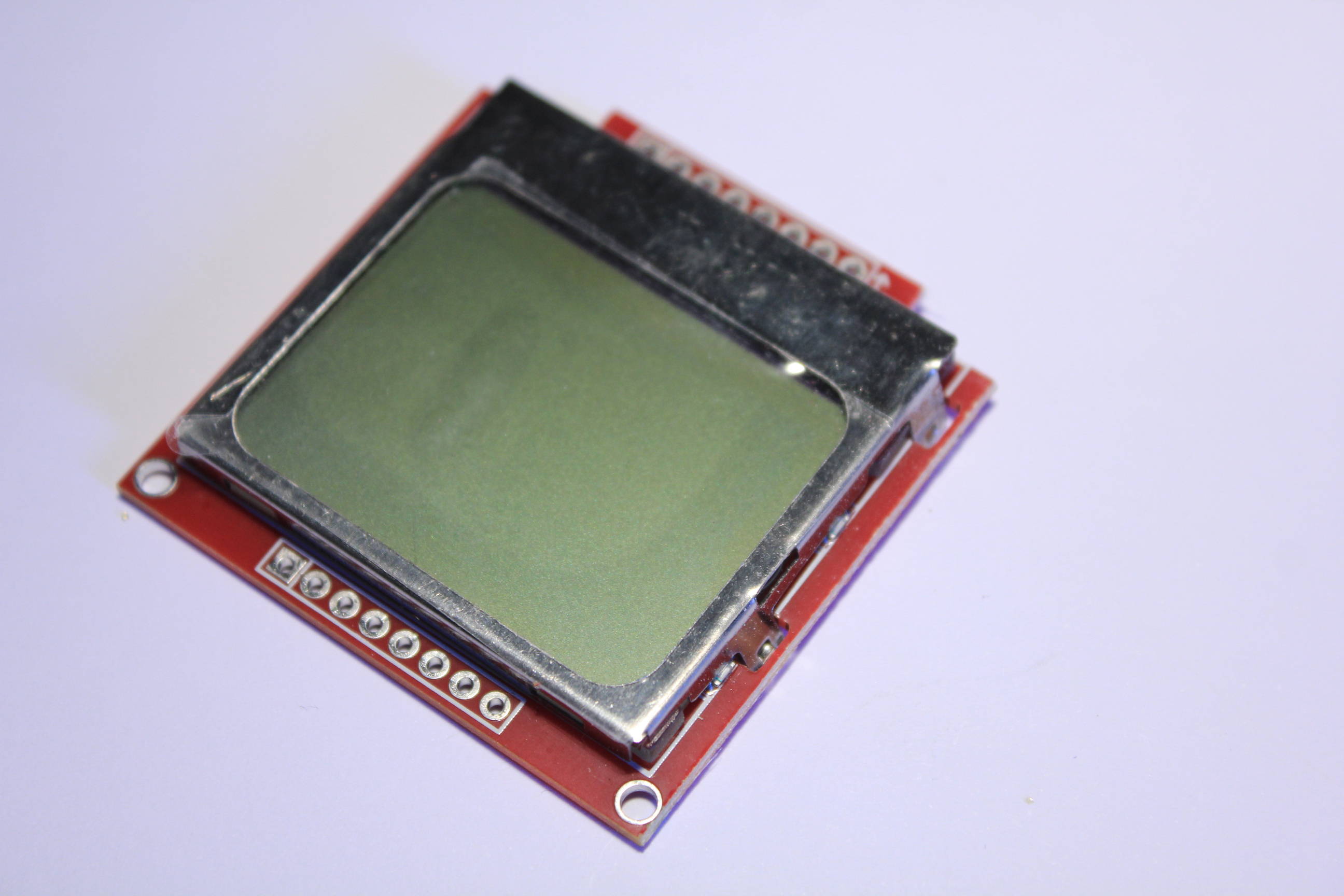
Now take the screen and the bended pin headers.
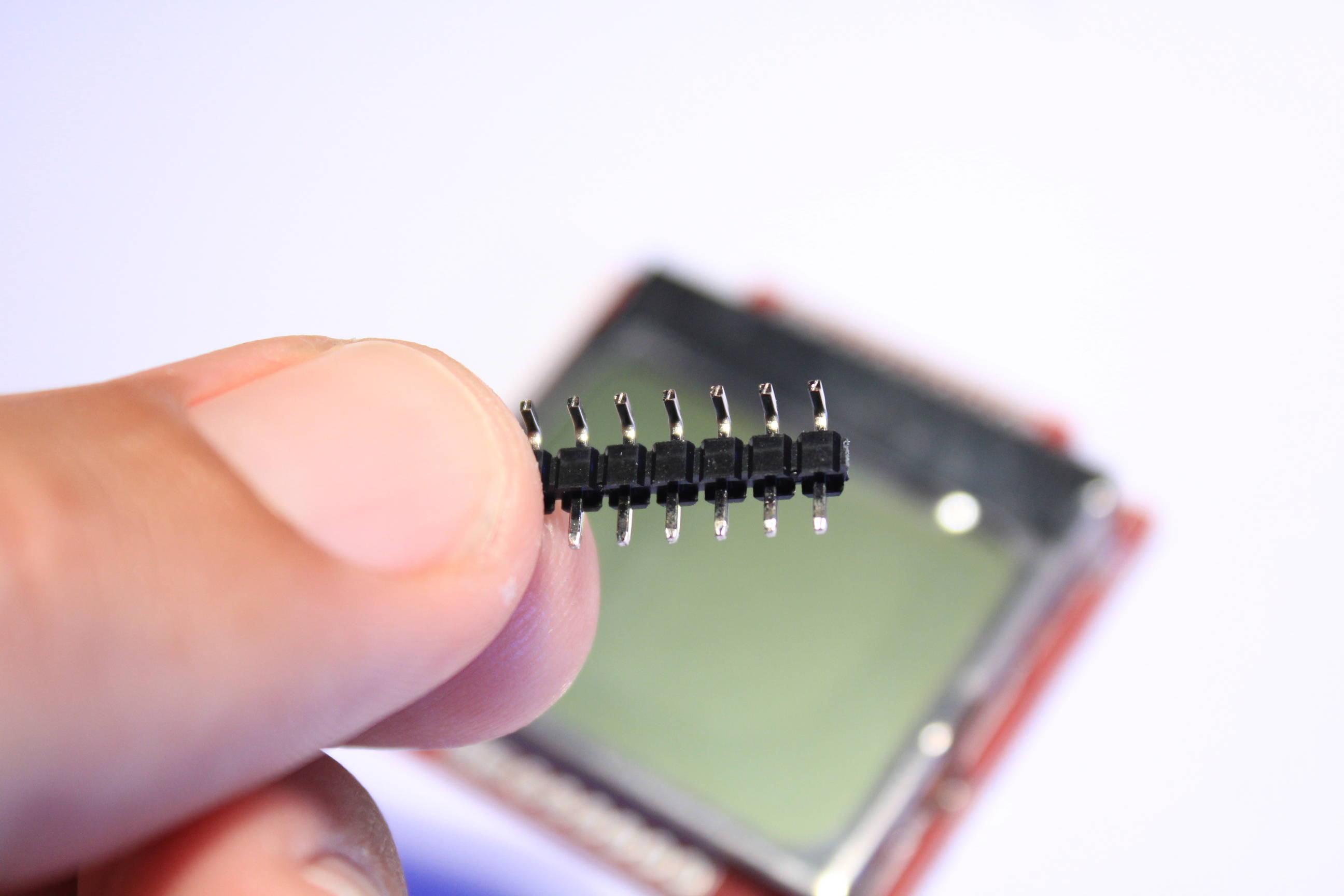
Don’t forget to solder just one pin first. Check the placement, solder and remove the insulation.