Hardware
Building tutorial summary
High component's boards soldering
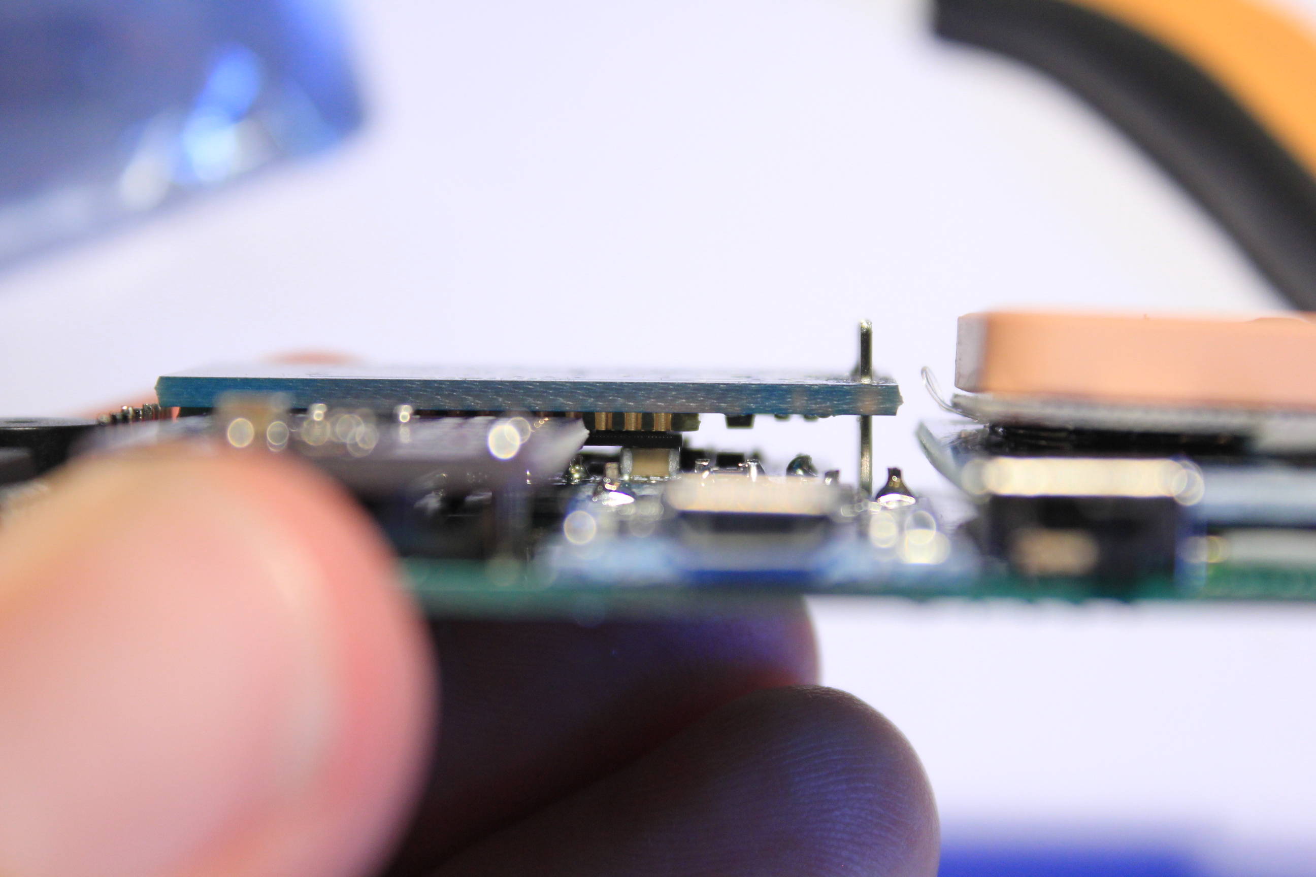
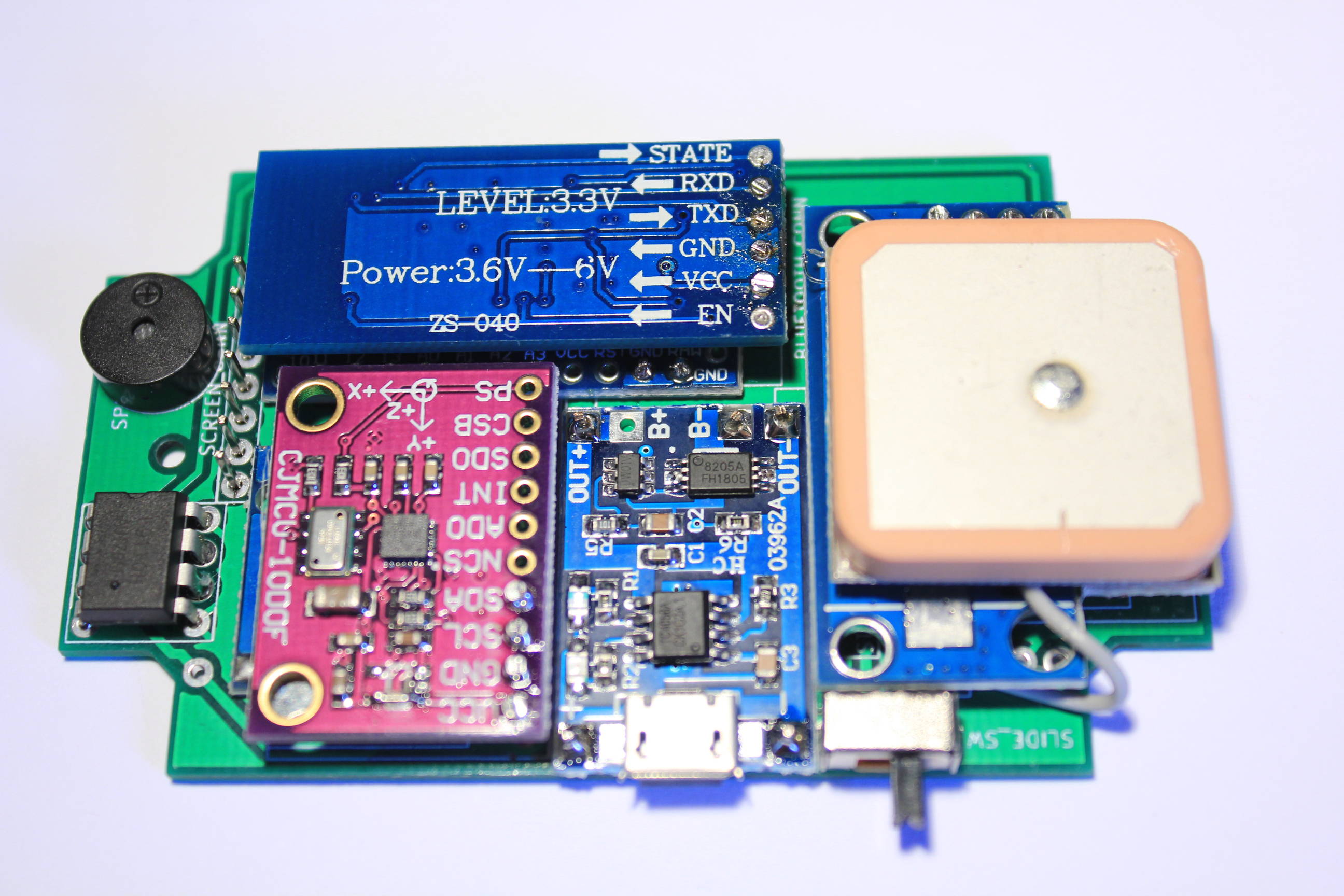
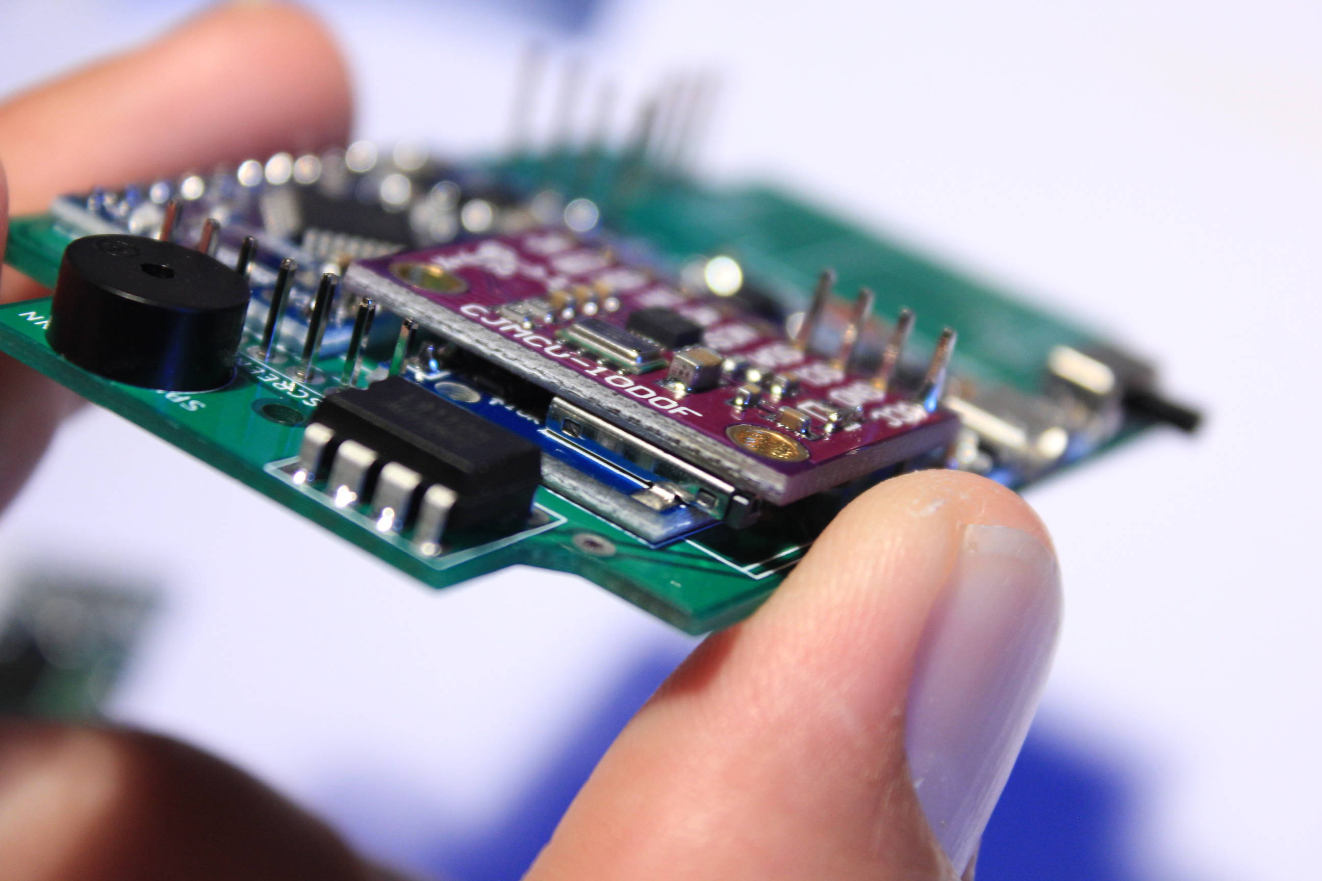
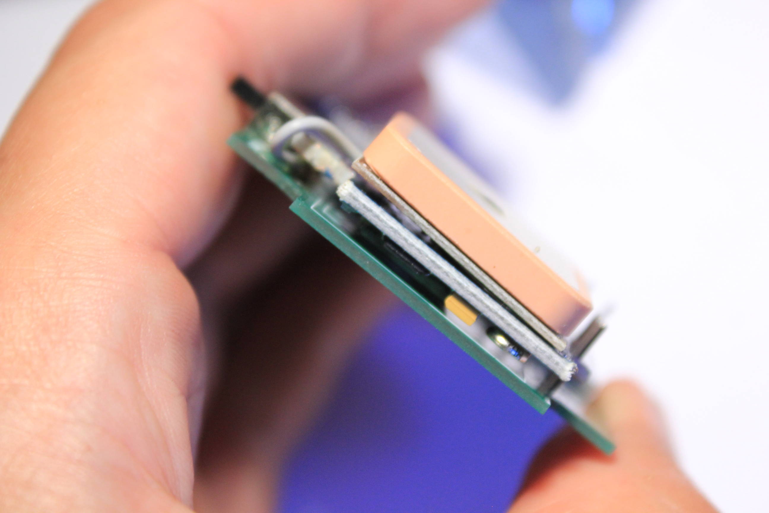
Take now the GPS, the bluetooth and the IMU boards. We need to solder them as close as possible of the PCB but keeping their placement horizontal.
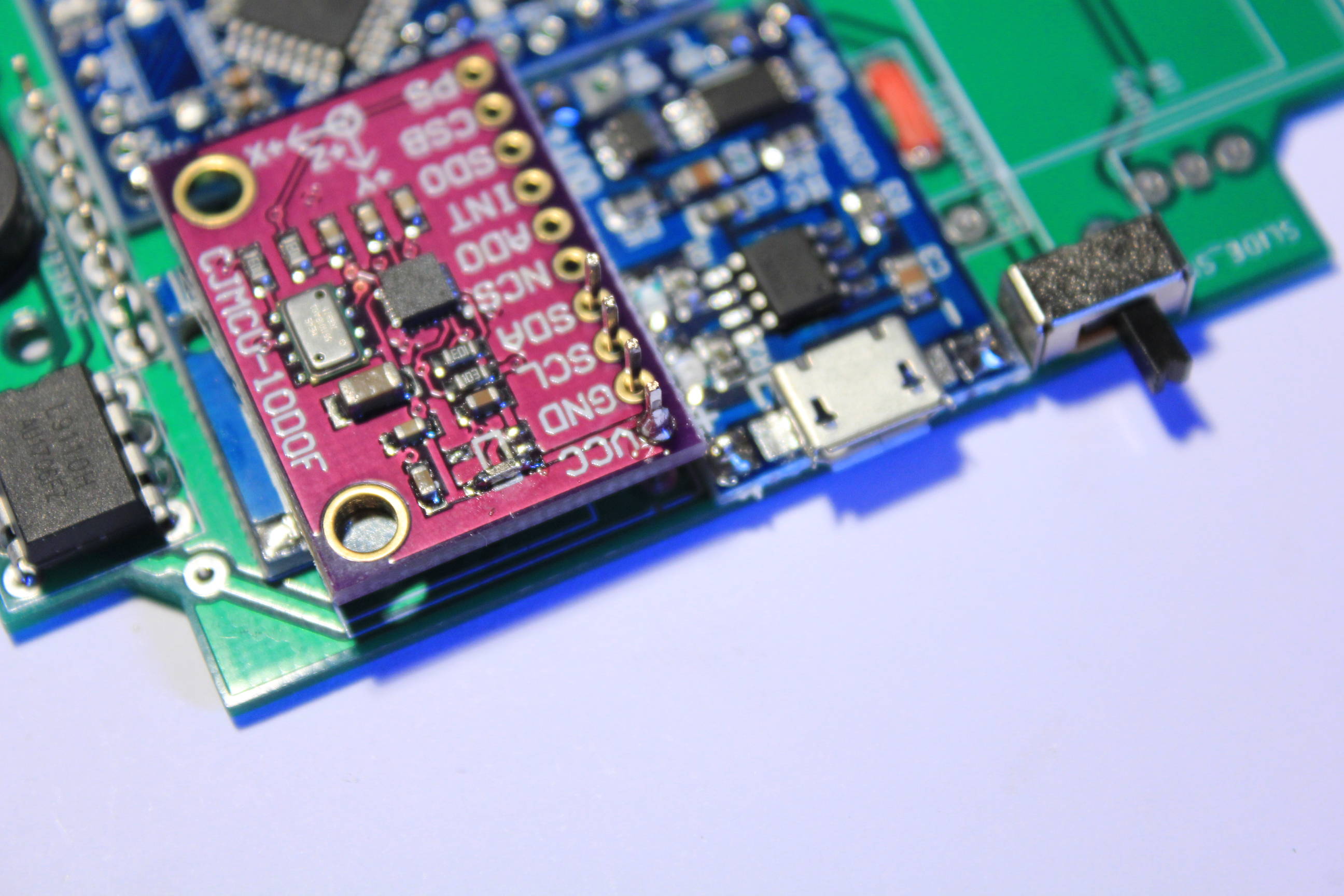
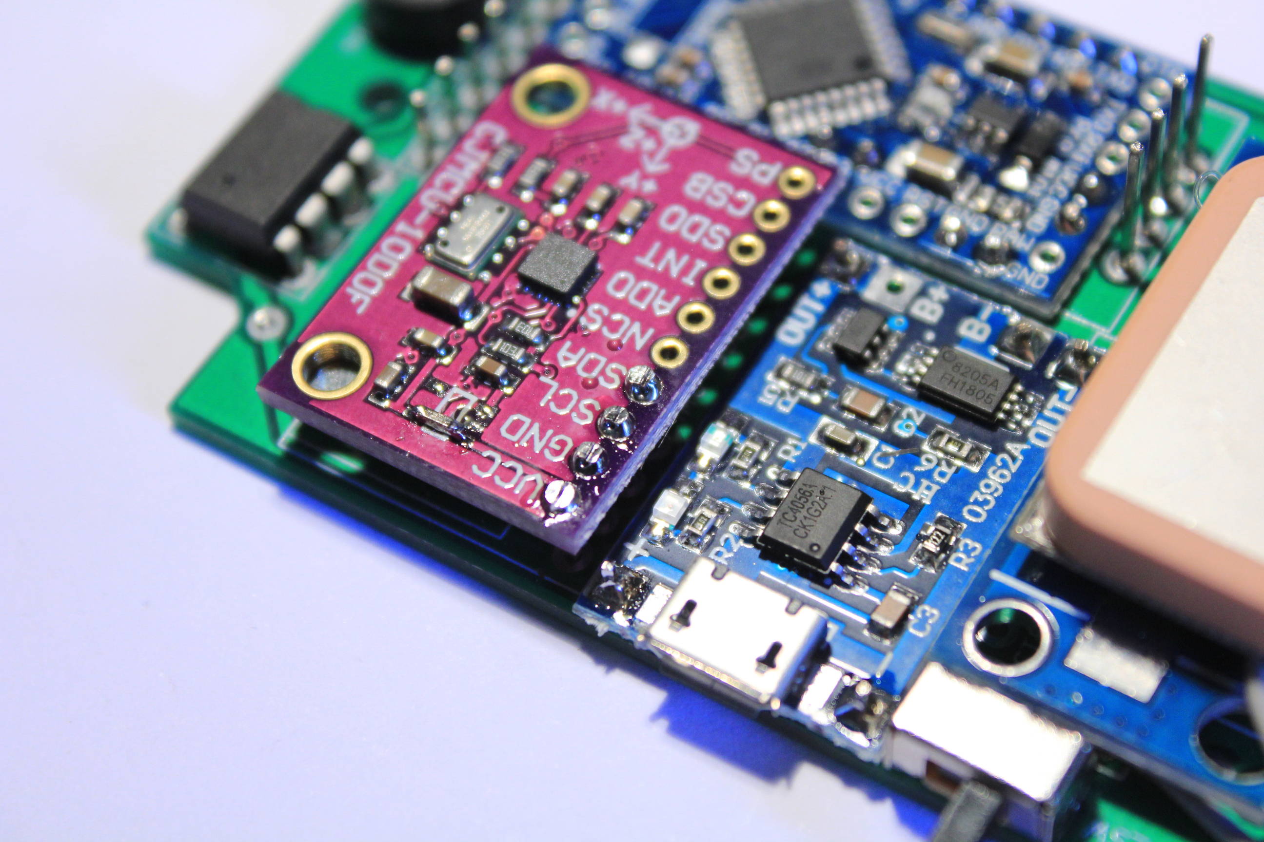
First place the IMU like in the picture below. Pay attention where you need to push on the board to keep it flat on the SD card reader.
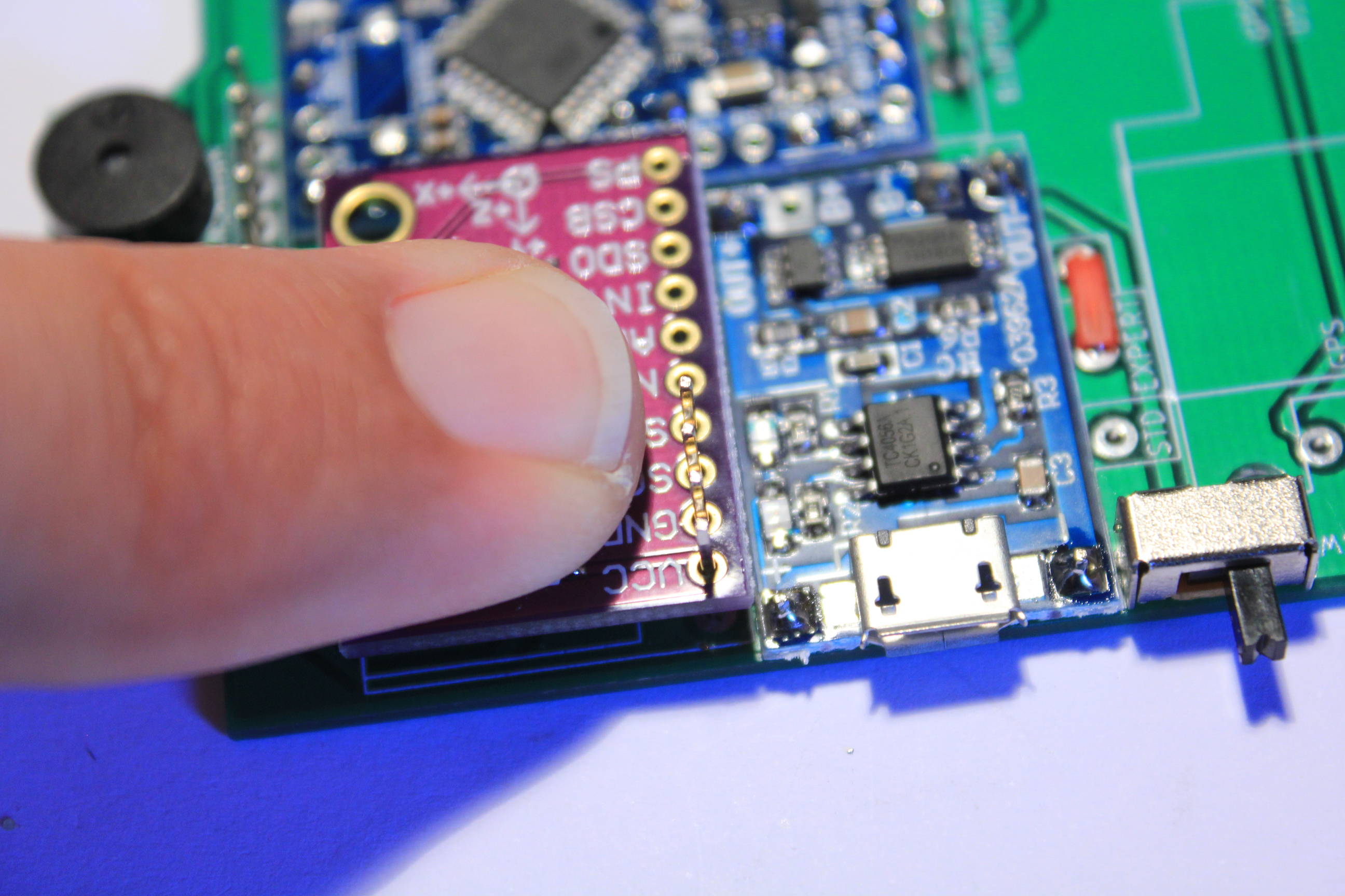
Solder just one pin and check that the IMU board is horizontal and flat on the SD card reader. Once the placement is good you can solder the other pins and cut the remaining tips.
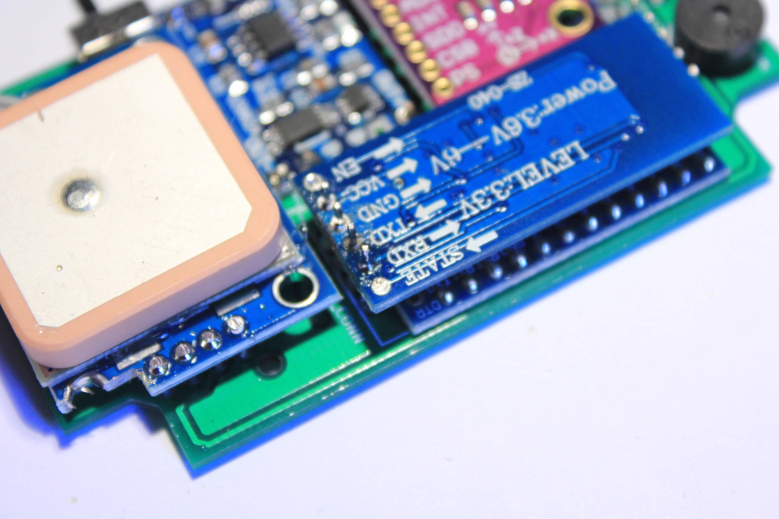
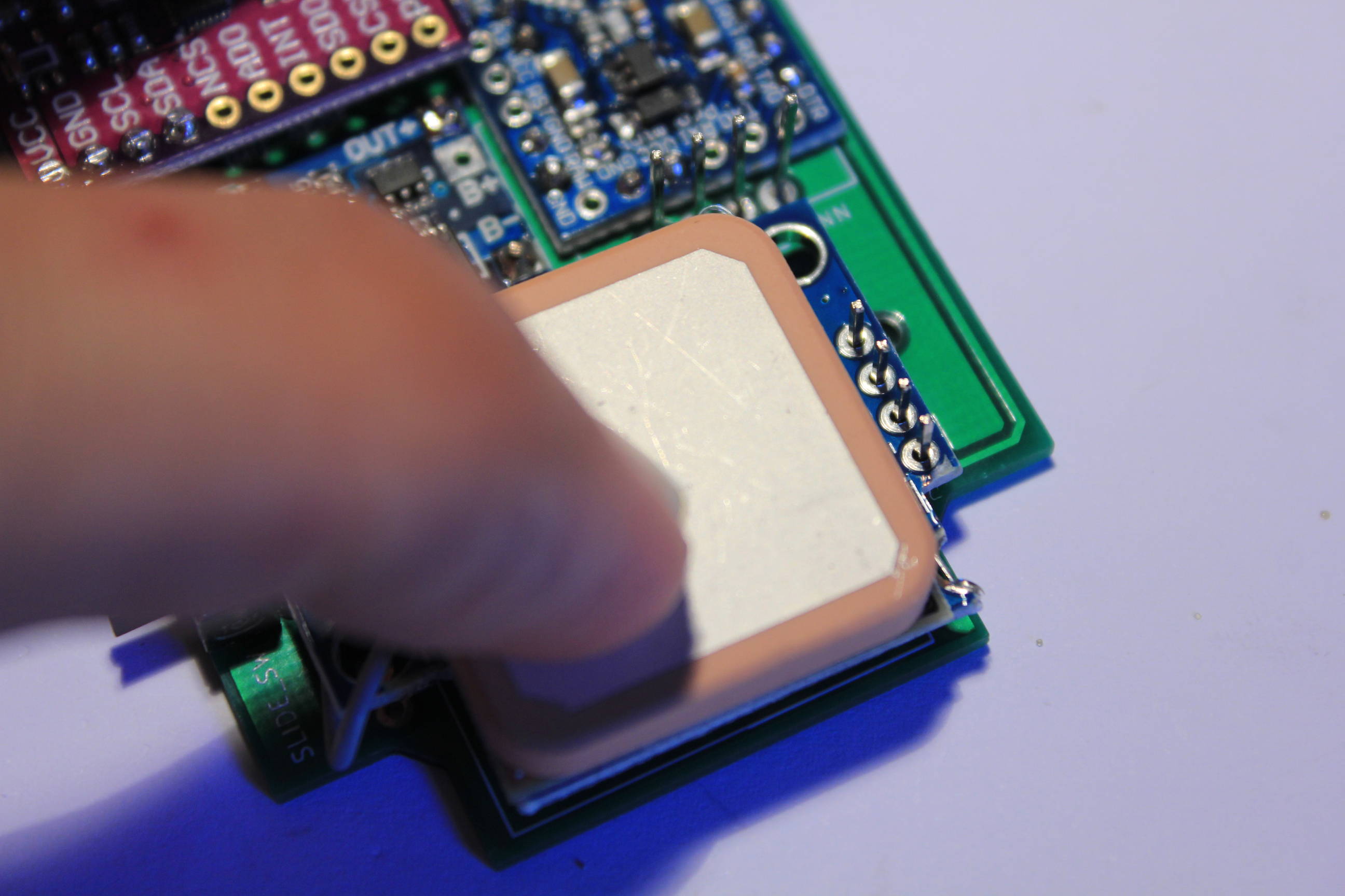
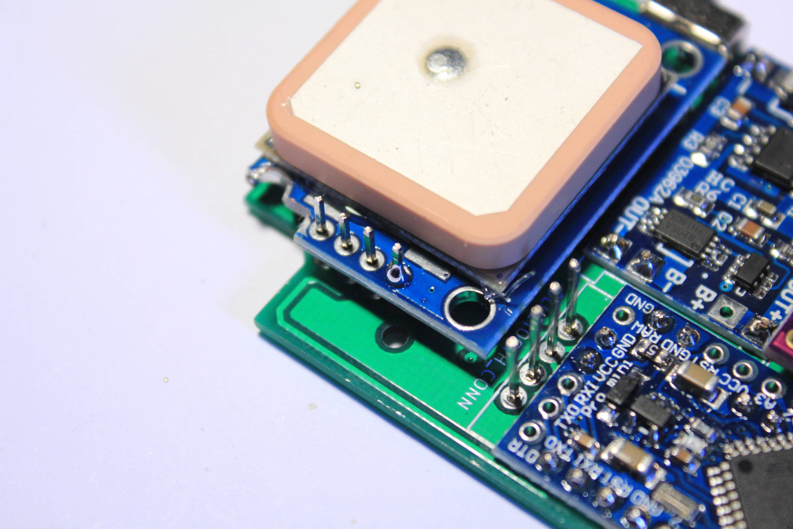
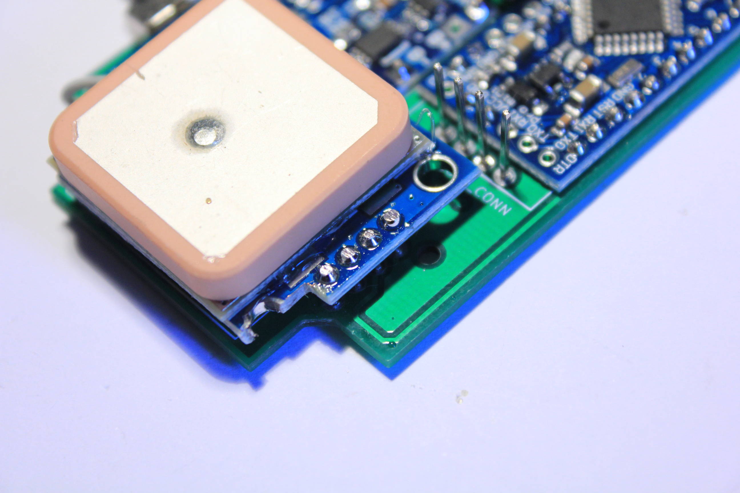
Same thing for the GPS. Check that the chip under the antenna is flat on the PCB.
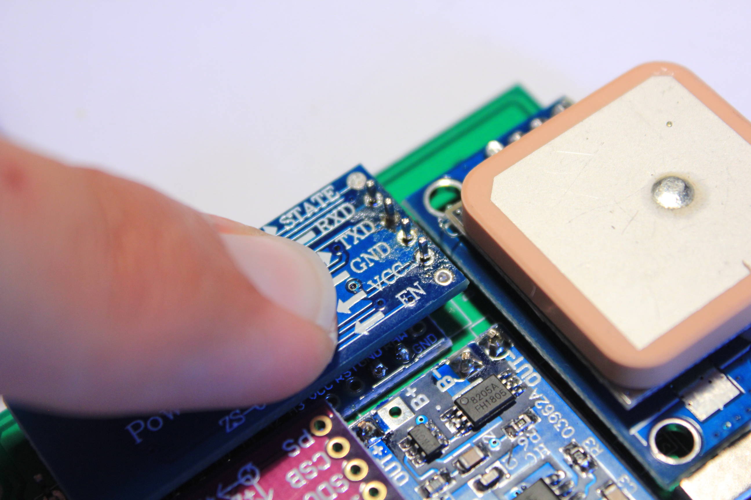
For the bluetooth module, check that the chip is flat on the two Arduino’s capacitors. Check also the board is parallel to the PCB. Be careful at the small resistor on the other side of the bluetooth module. Don’t apply too much pressure. Don’t forget to cut the pin’s tips.